Every year, my friends and I bring a plethora of robots to compete at Dragon Con's Robot Battles competition. It includes 1 and 3 pound robots for their Microbattles segment on Sunday, and 12 and 30 pound sumo robots for their main event on Monday.
As tradition, out entries must consist of several "assbots" among our serious entries.
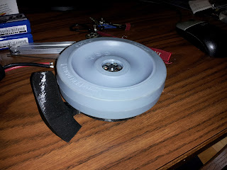
Wheel! (Colson Bot)
After four years of being relatively invincible, I have decided to force-retire DDT. Replacing it at Dragon Con will be the beloved assbot dubbed "Colson Bot".
In the mid-2000's, the arena hazard for micro battles was a colson wheel attached to the output of an angle grinder. It was well known for its overpowering hits that often determined the outcome of the matches. Colson Bot was designed to look and function very similarly... without the stability of being bolted to the ground.
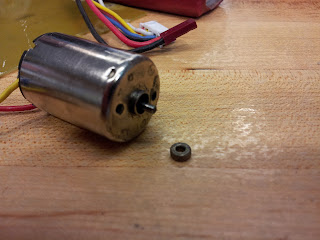
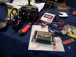
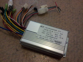
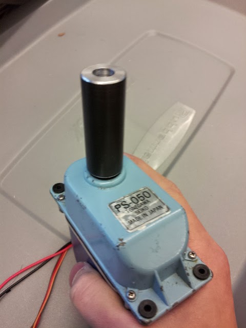
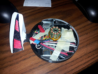
Being an assbot, I had determined that the budget would be minimal. Luckily I had just disassembled DDT and Prop Quiz which left me with several options for controllers and motors. I elected to recycle the gearmotors from Prop Quiz and the electronics from DDT.
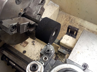
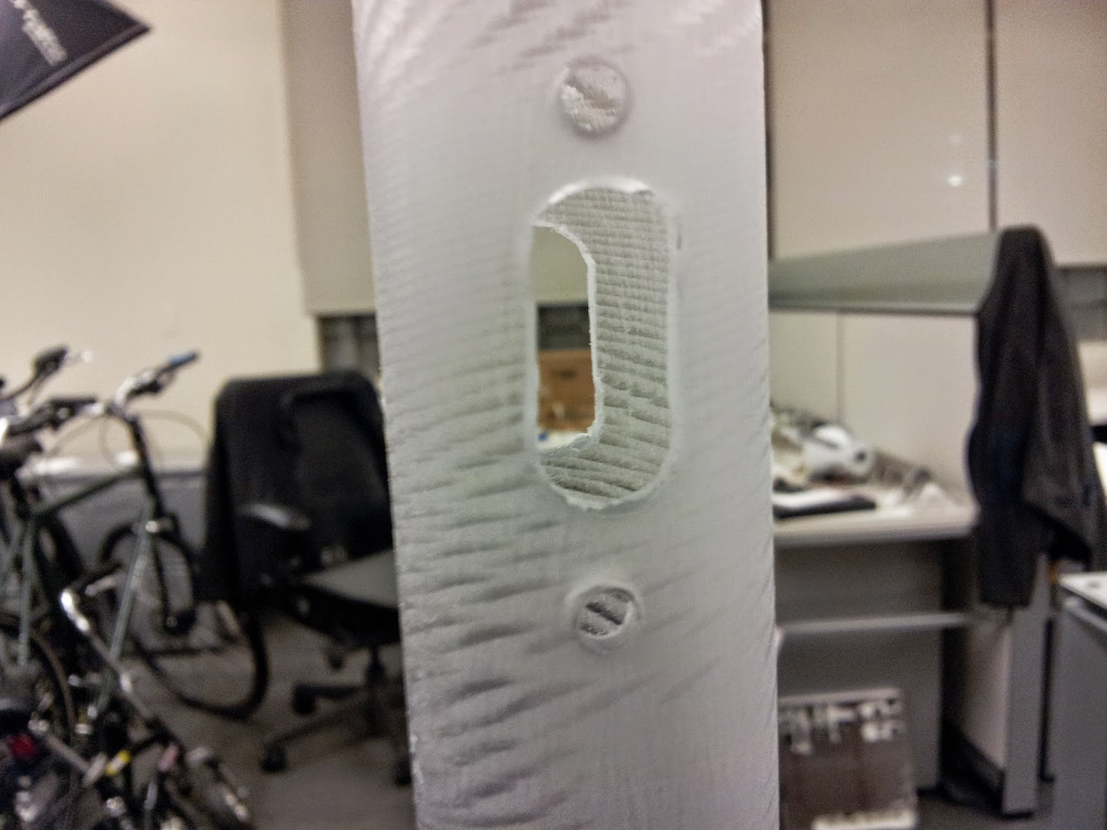
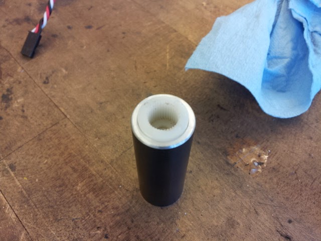
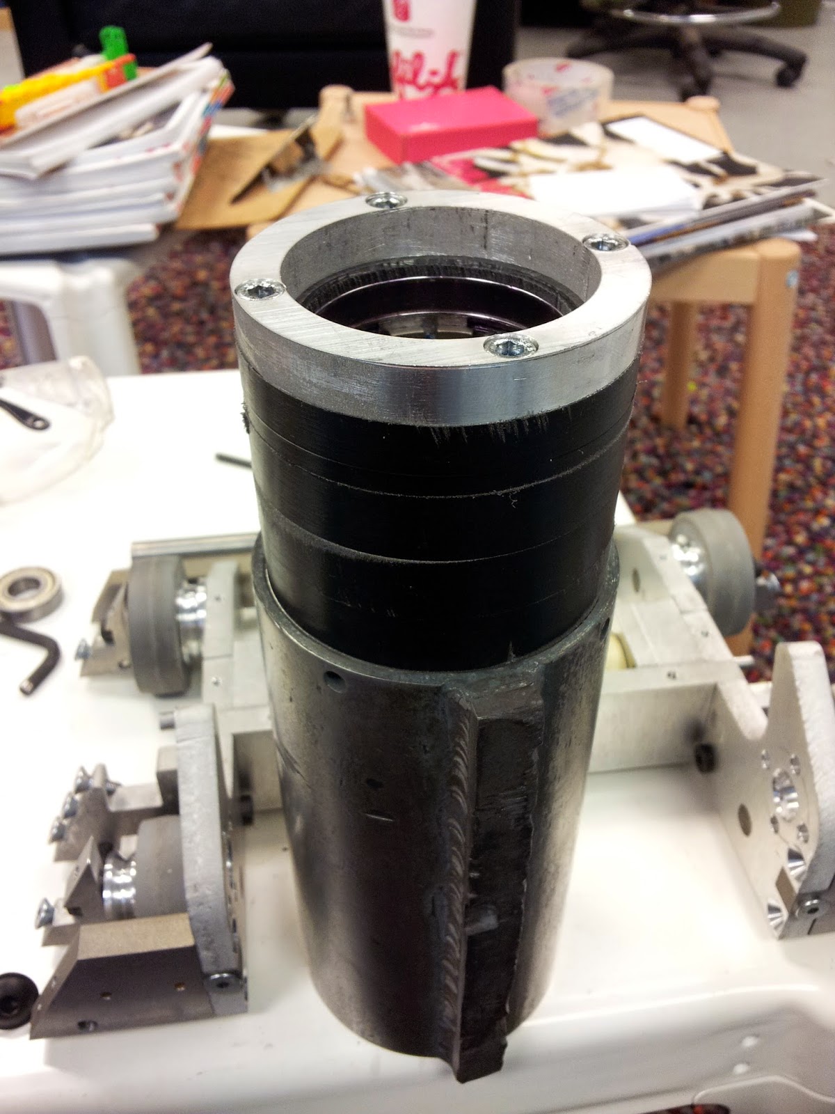
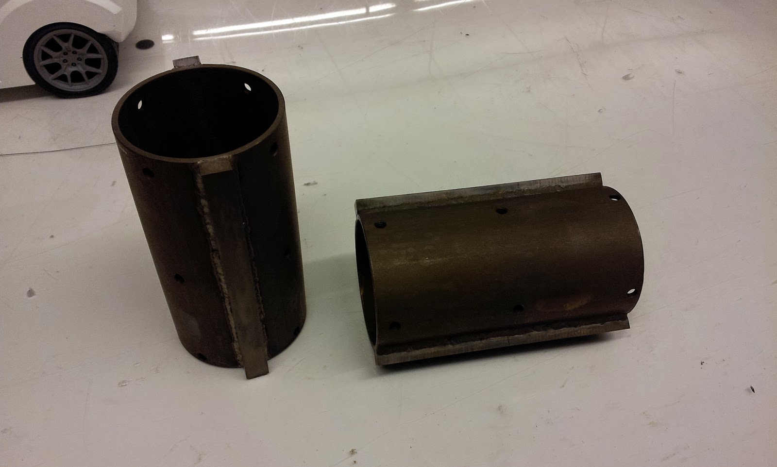
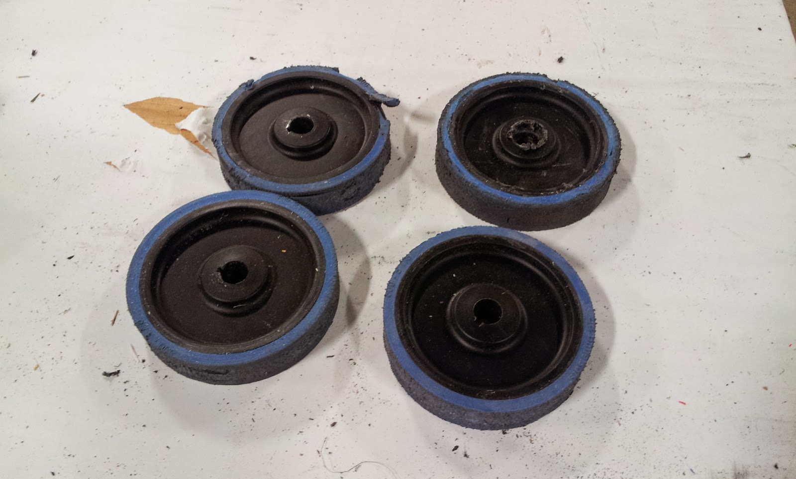
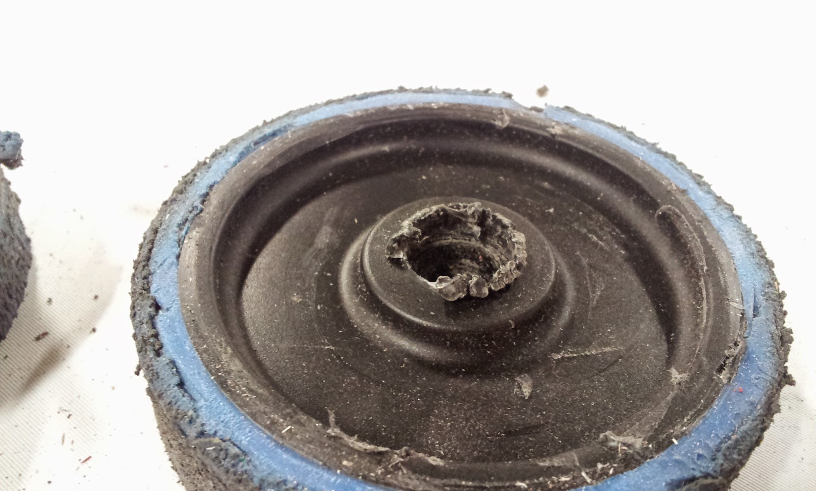
There were two main steps to the design: finding a colson that could be bored large enough to fit the electronics and making a chassis small enough to fit in that bore. Given I had already selected my parts, I decided to reverse order design and build the chassis first.
![]()
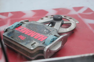
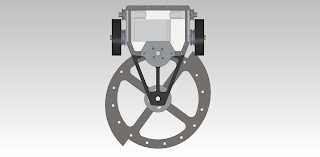
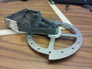
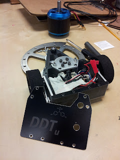
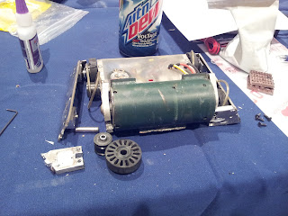
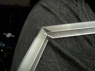
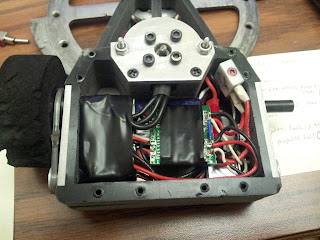
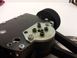
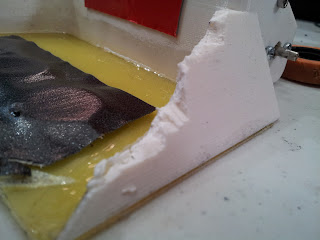
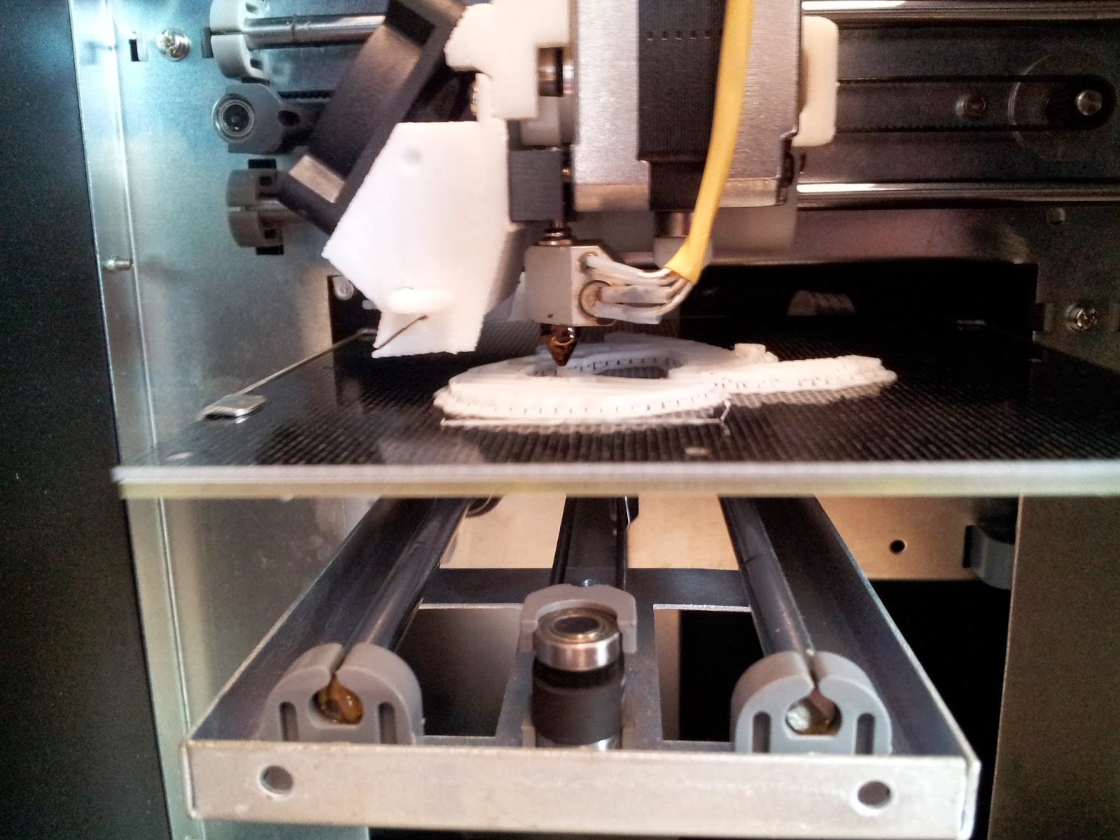
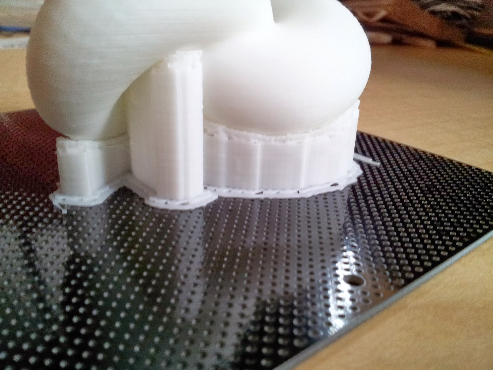
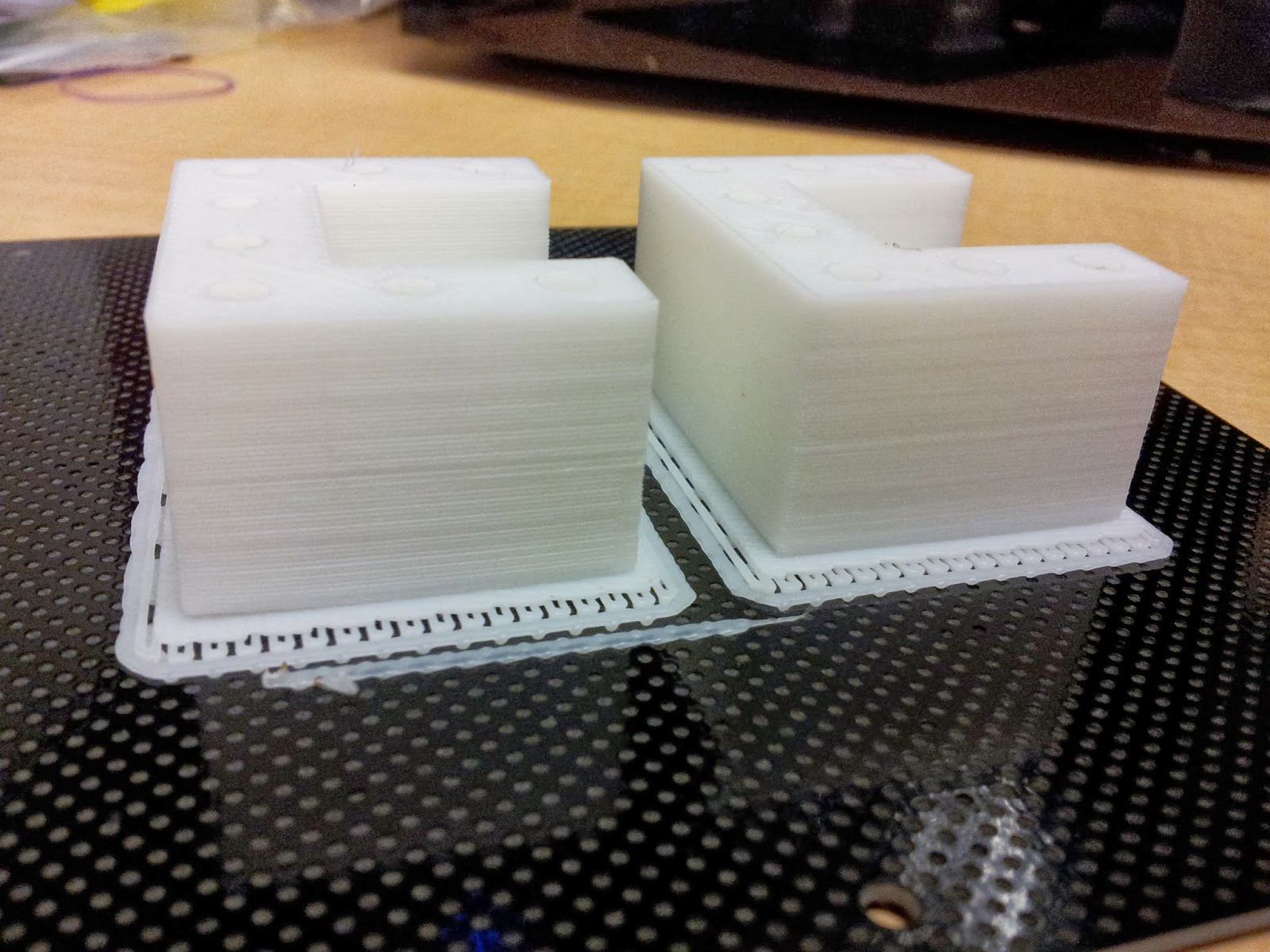
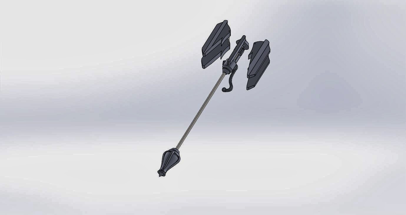
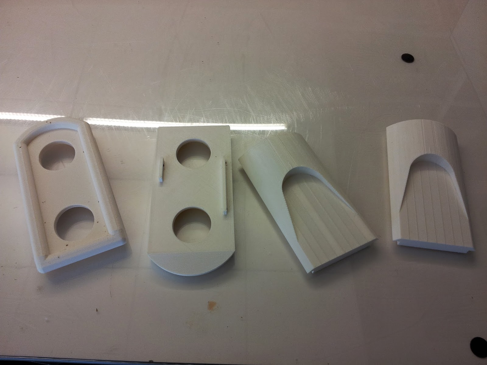
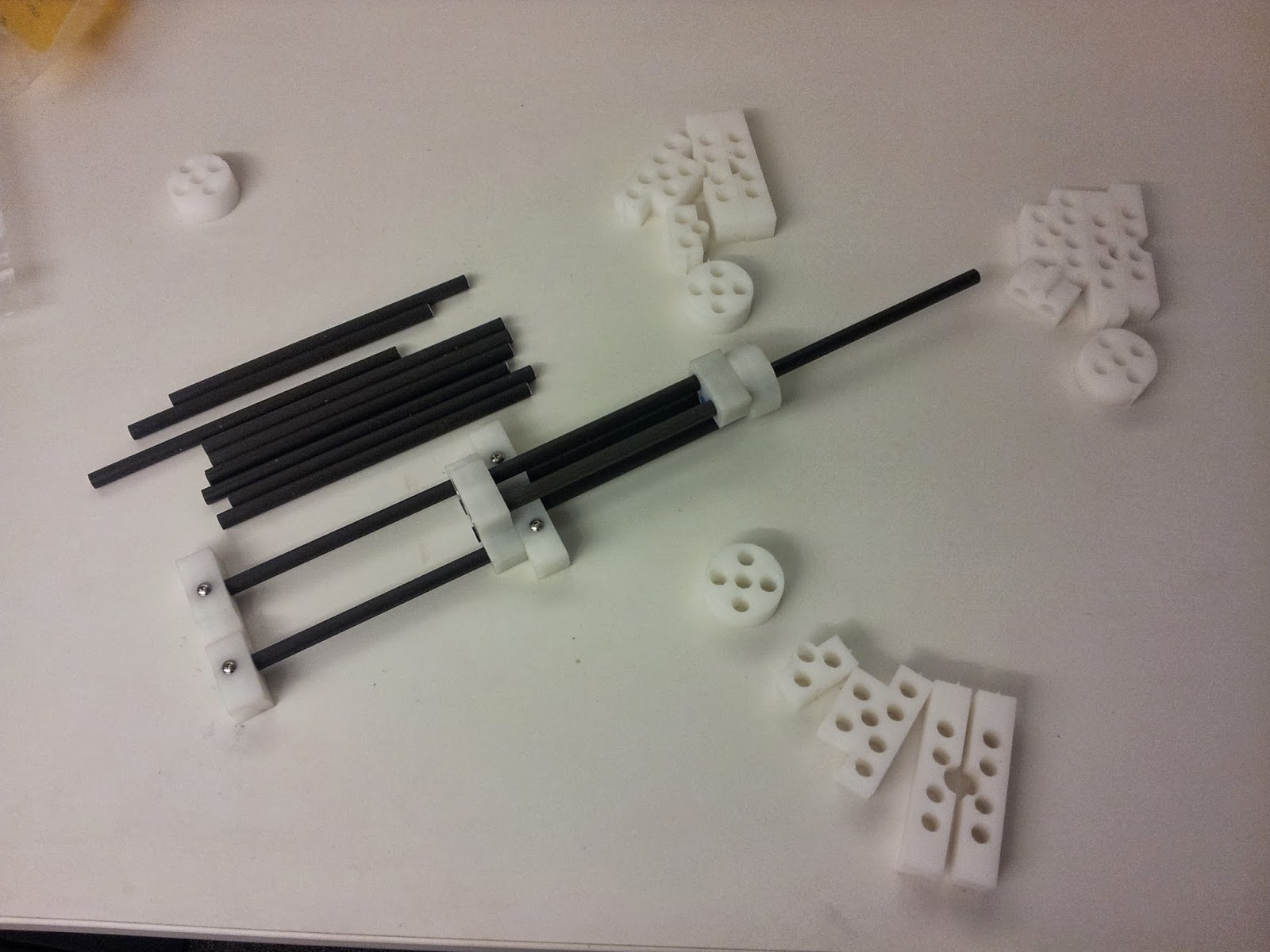
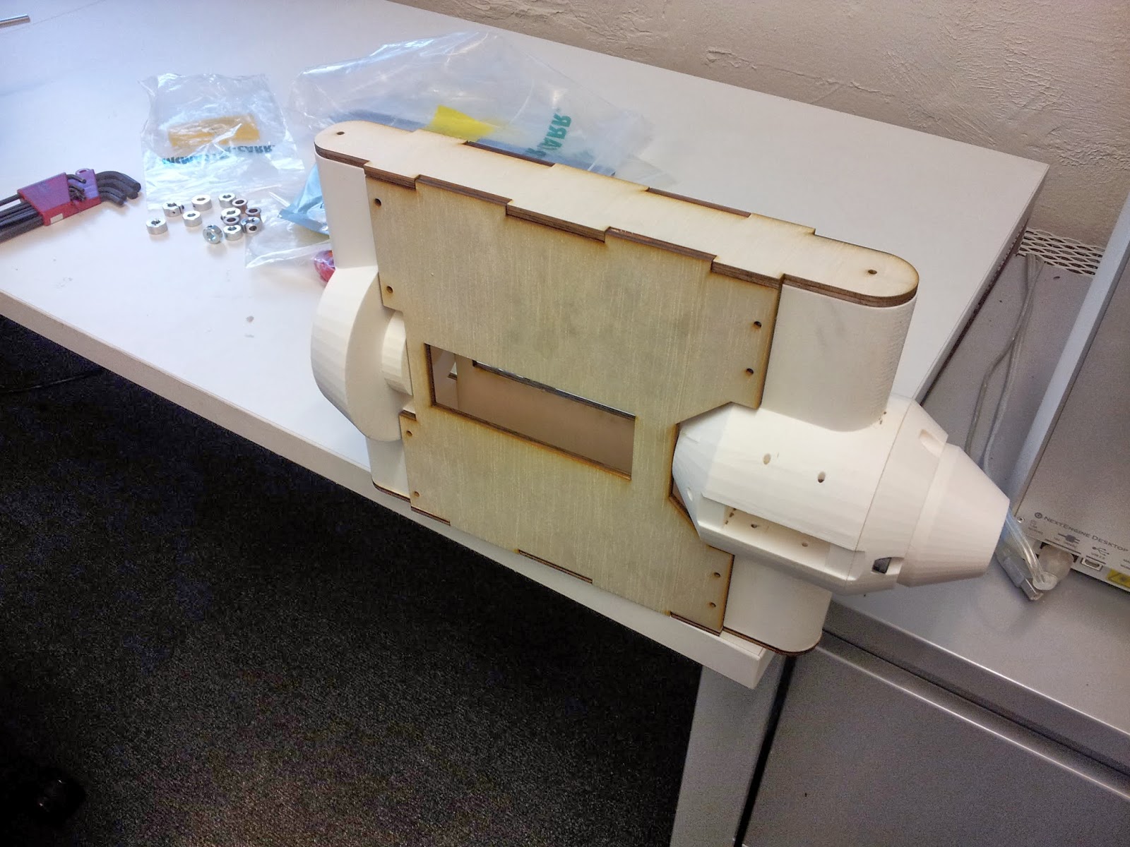
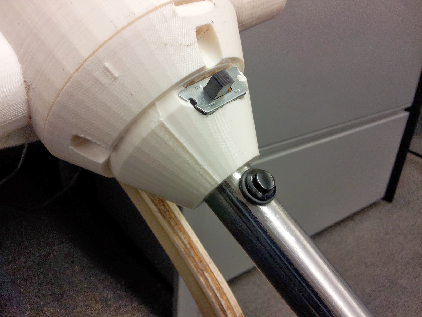
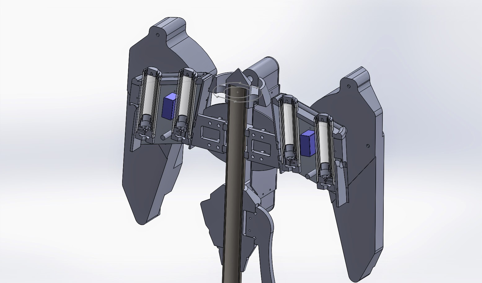
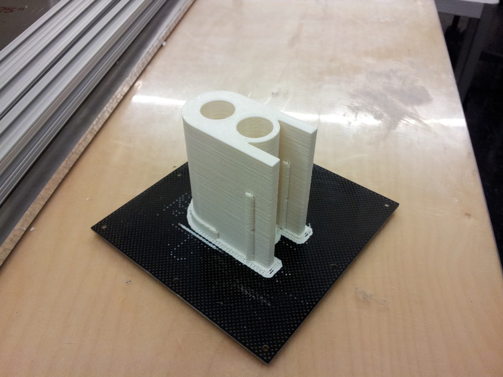
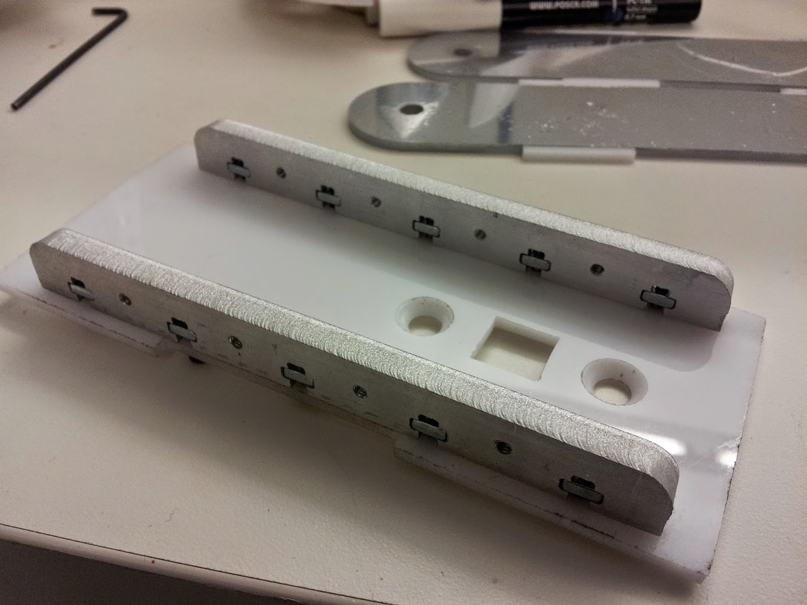
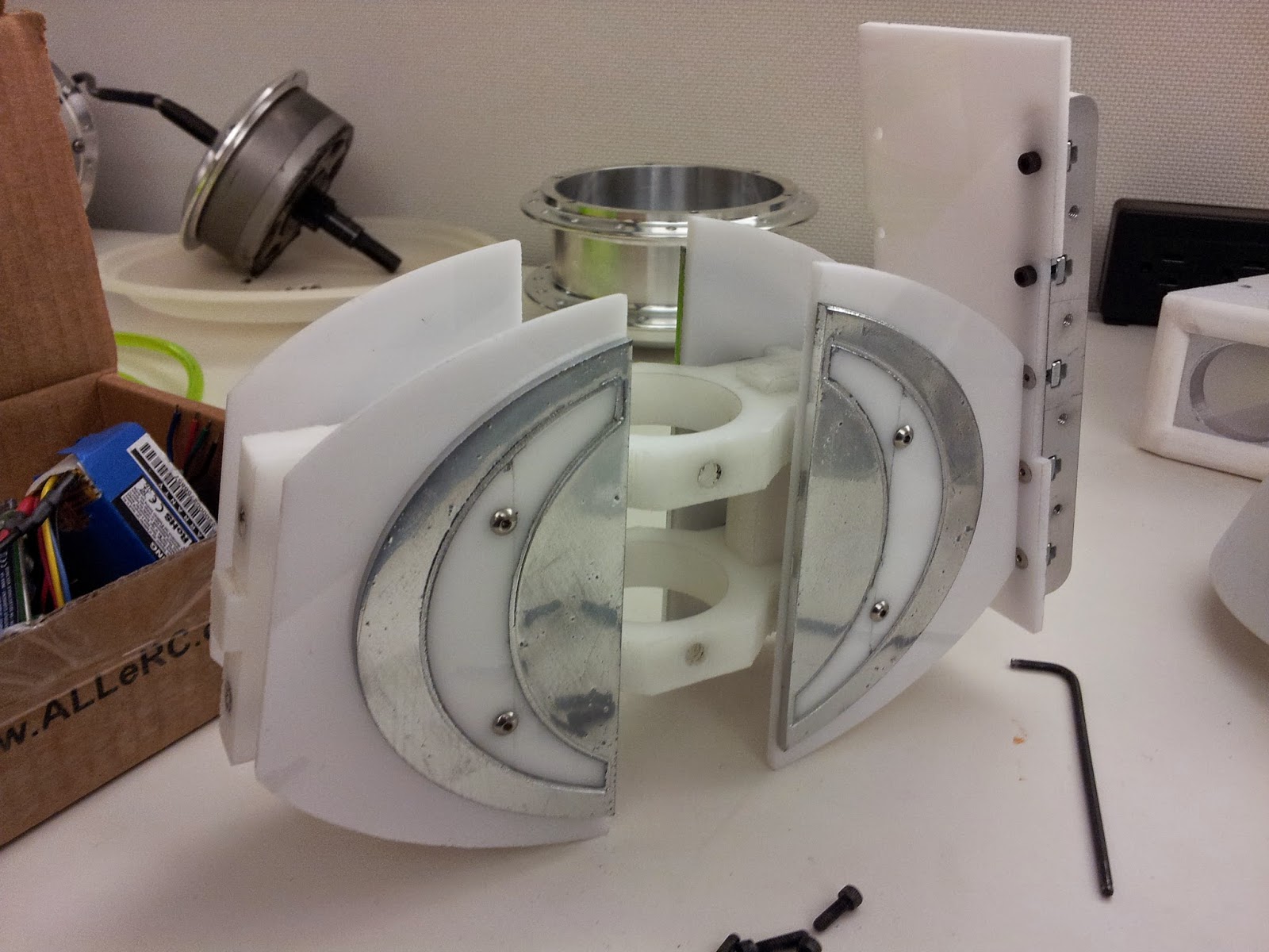
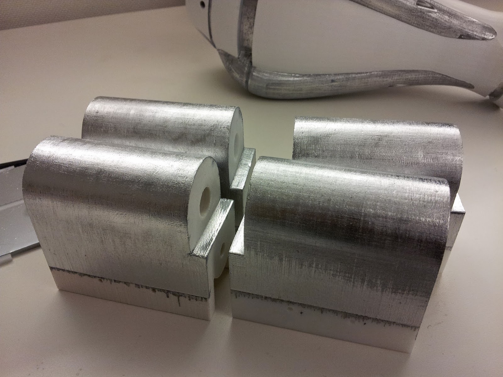
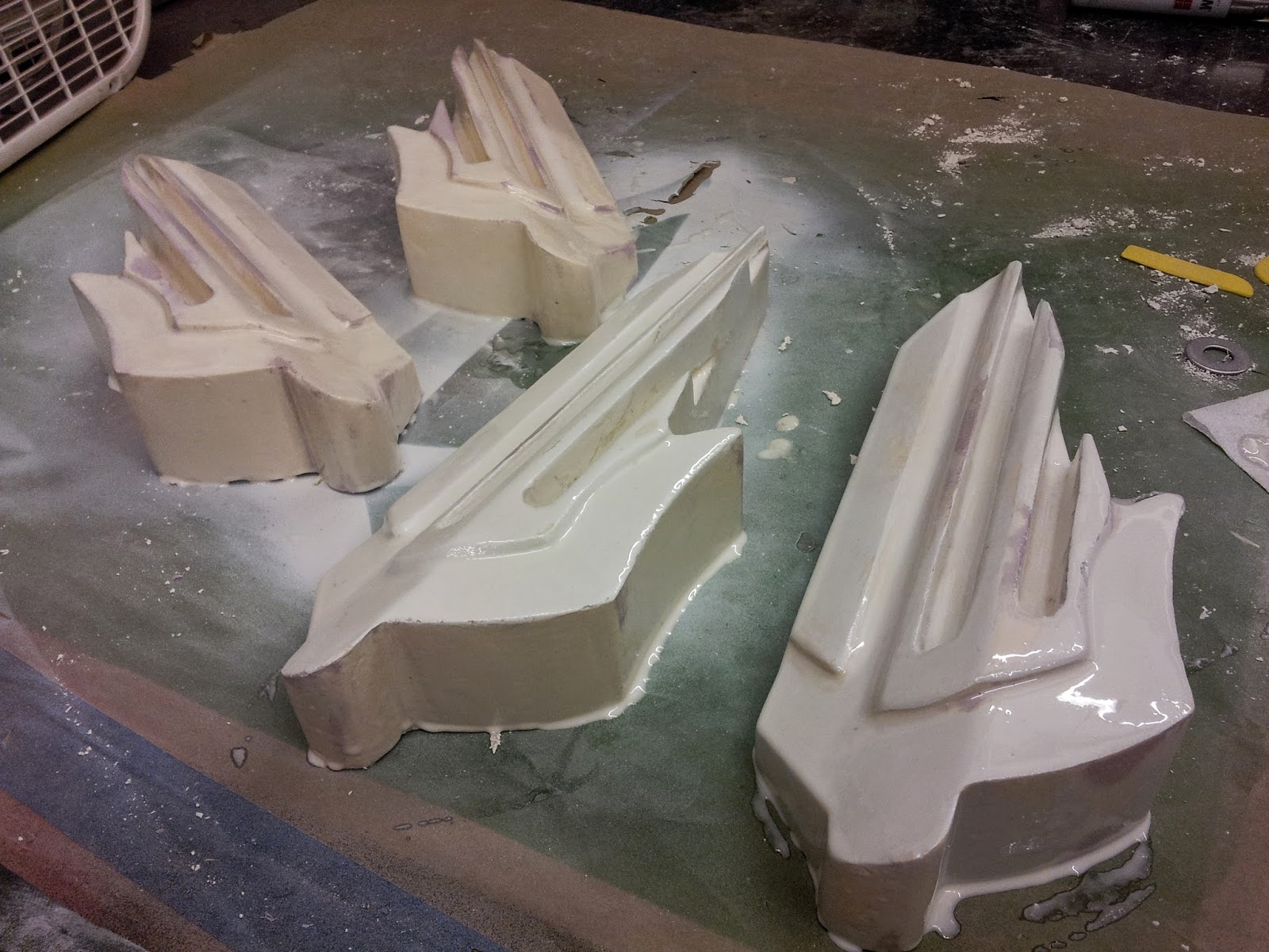
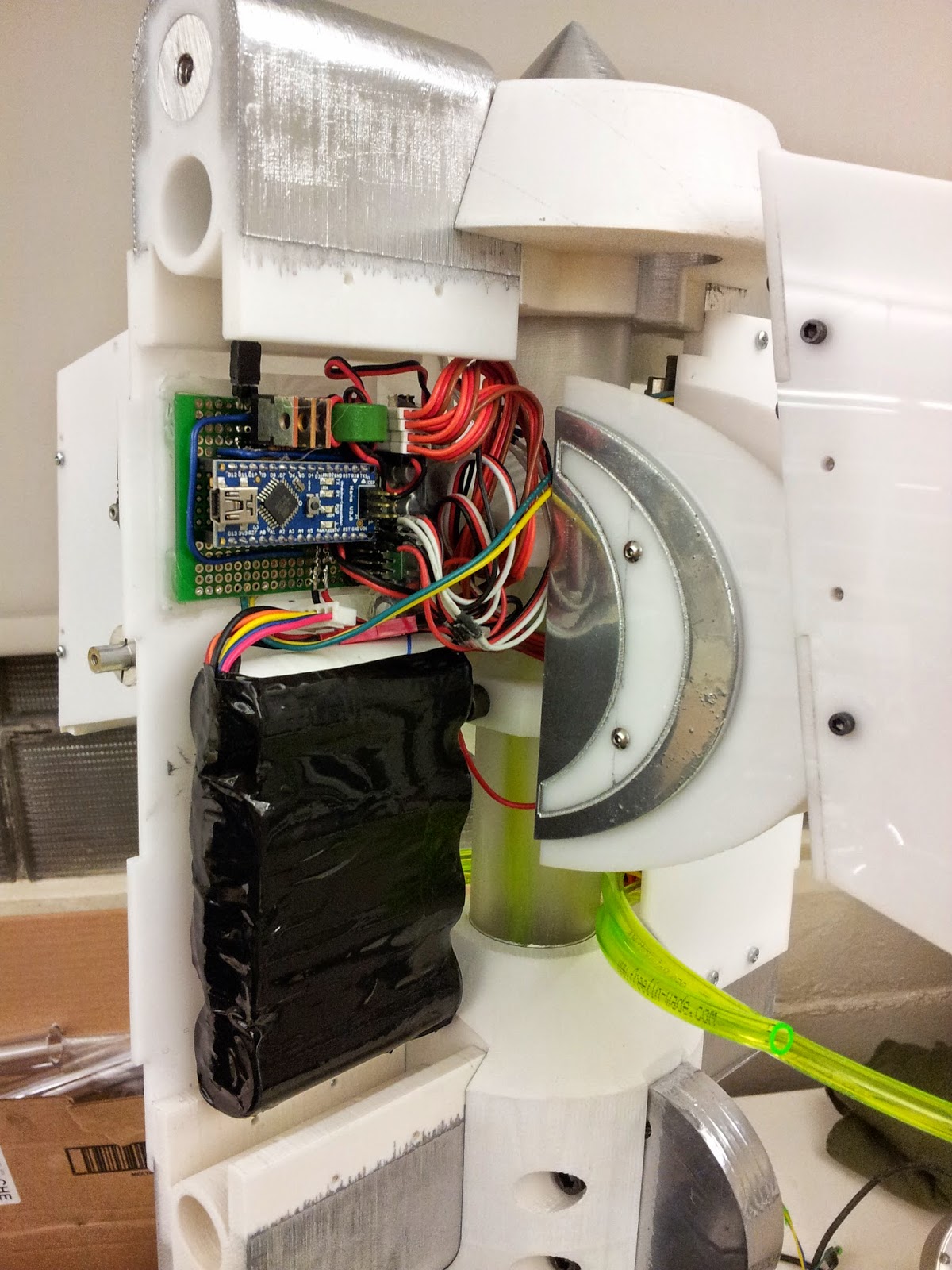
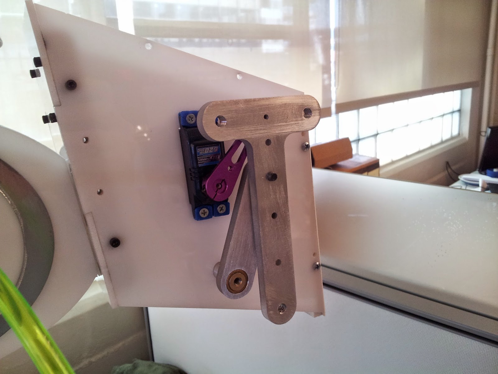
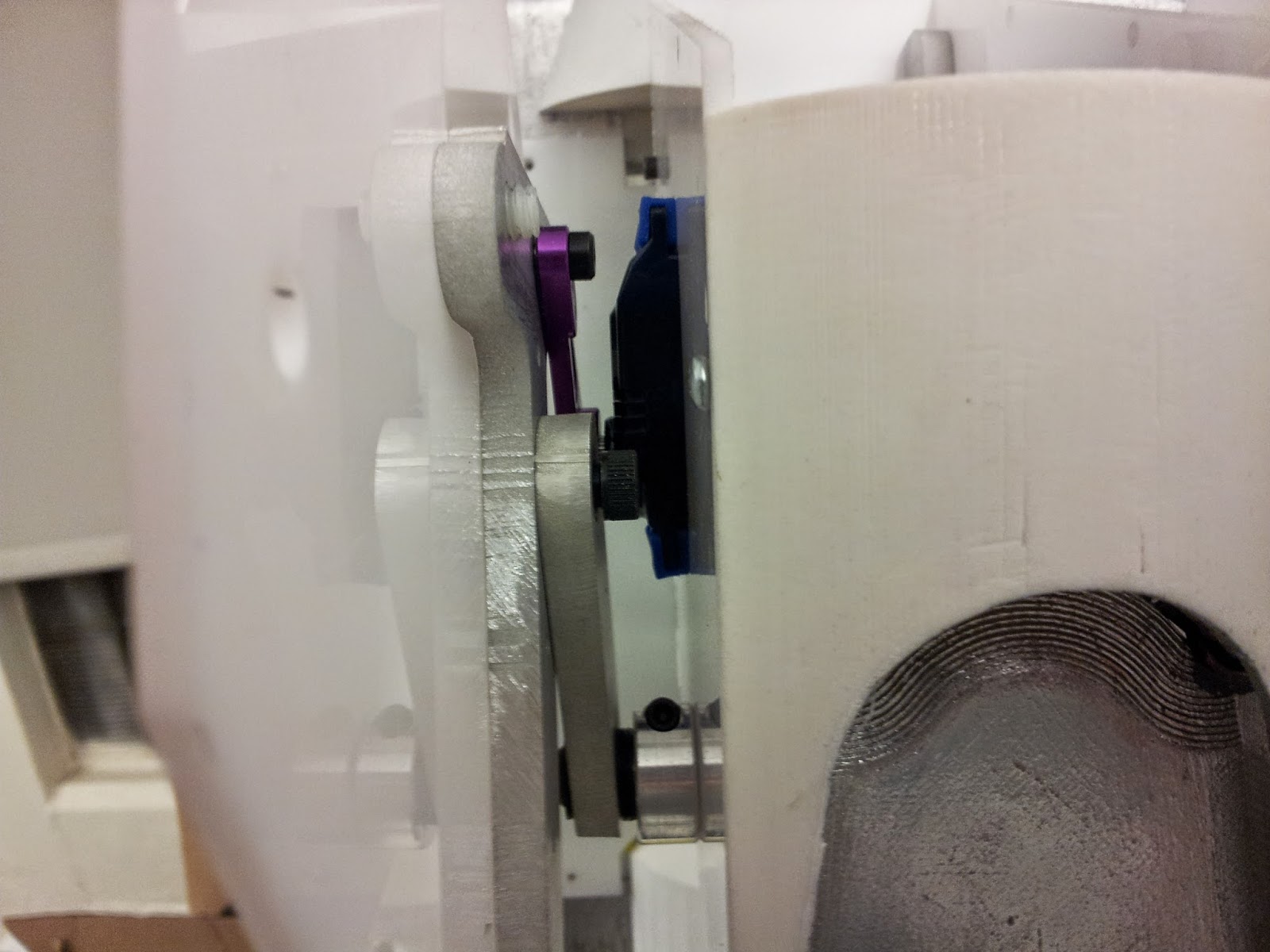
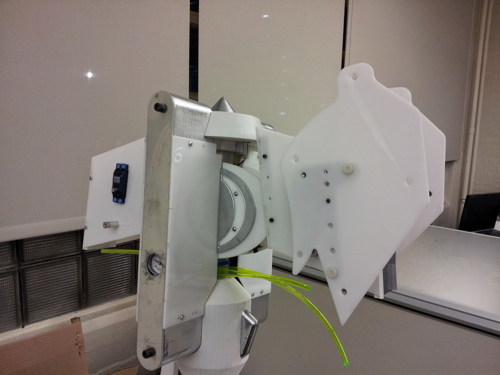
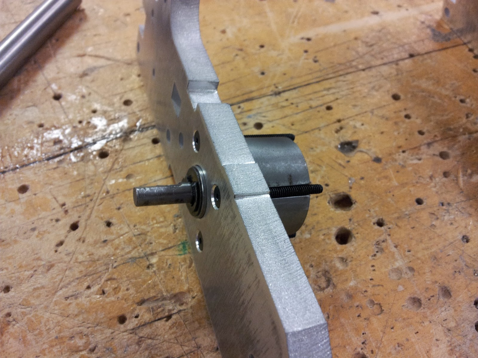
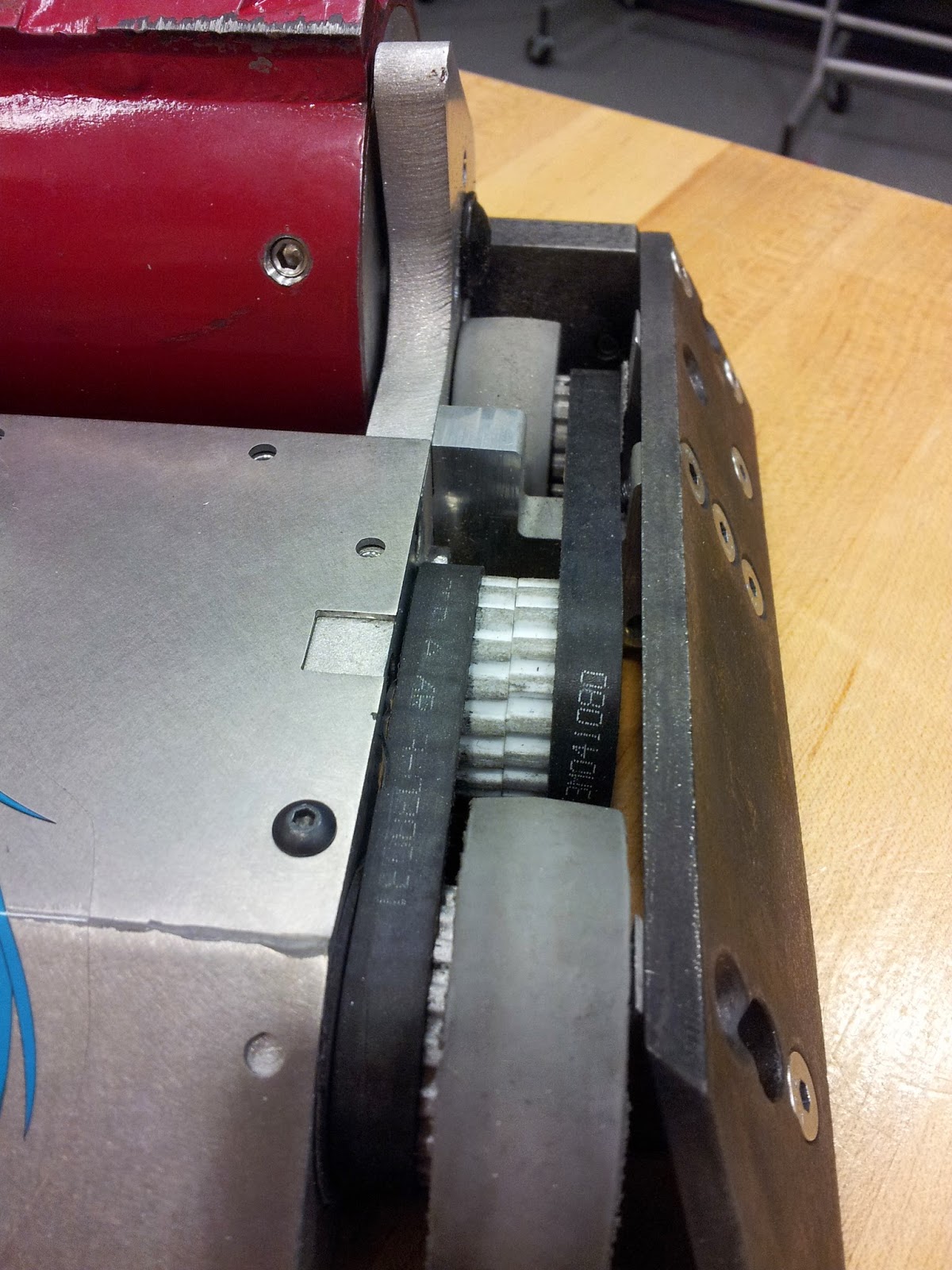
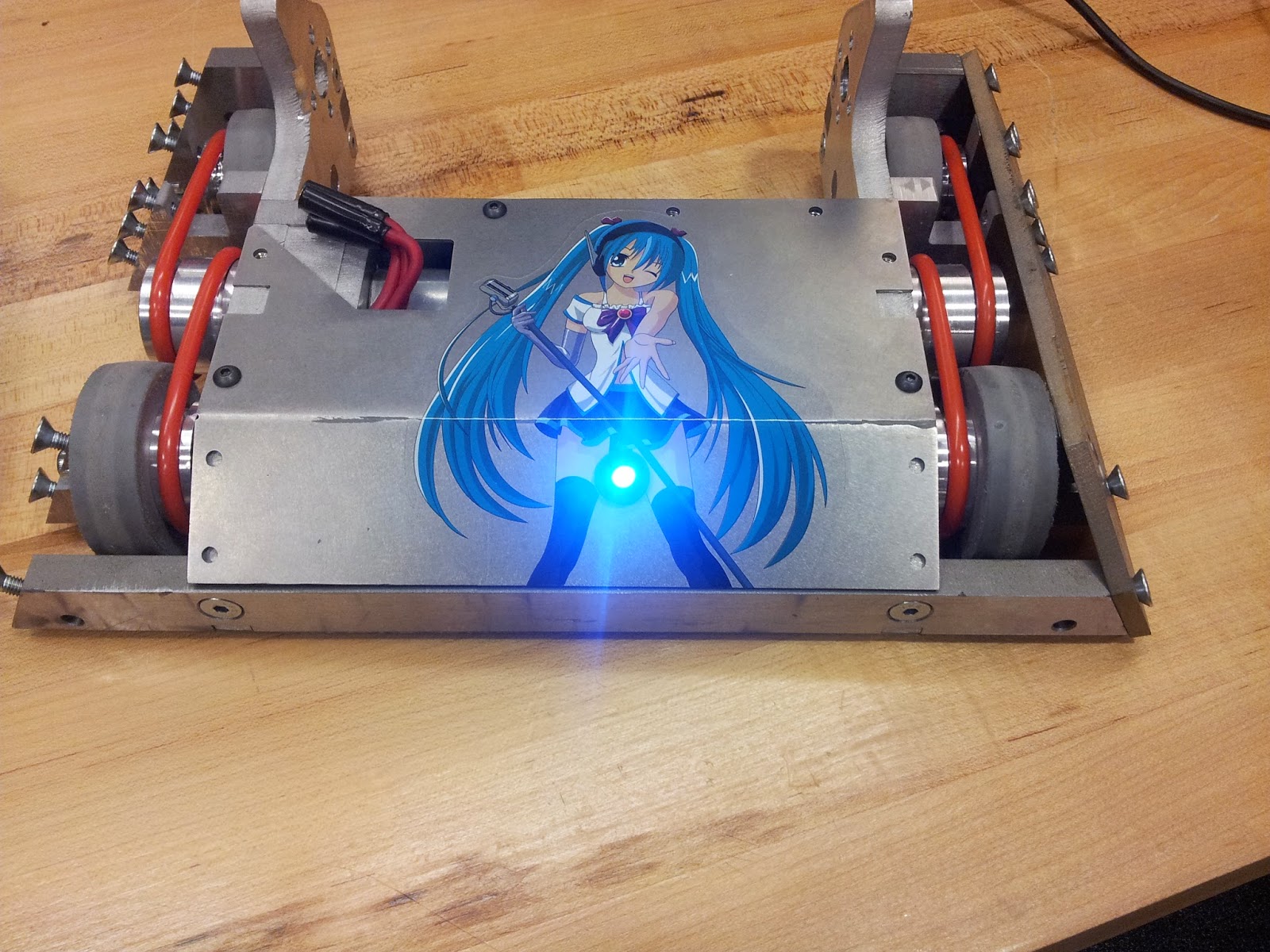
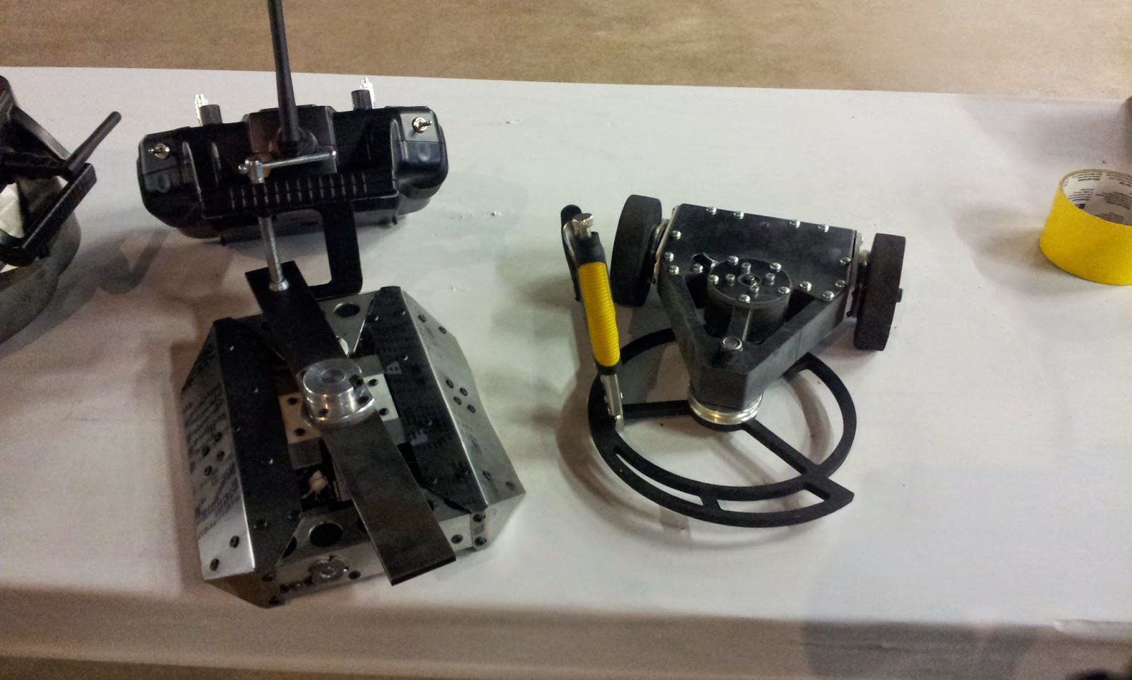
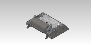
Treads would have been ideal to maximize traction, but could not be done with the space constraint. Instead, the design used is pictured above. The robot is designed in layers. The bottom layer (including the wedge) is 3D printed out of PLA on one of the Invention Studio Ultimakers. The top section is waterjetted polycarbonate screwed on from the bottom of the robot. This top section mounts the Esskay 400xt brushless motor that directly drives the colson wheel (not pictured). I fully expect the 3D printed chassis to snap somewhere.
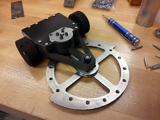
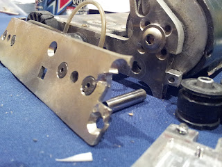
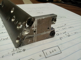
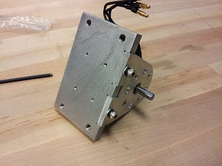
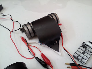
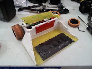
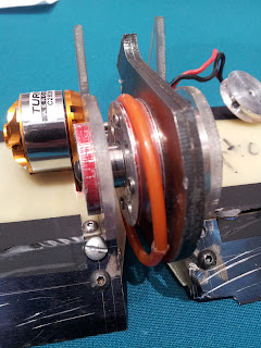
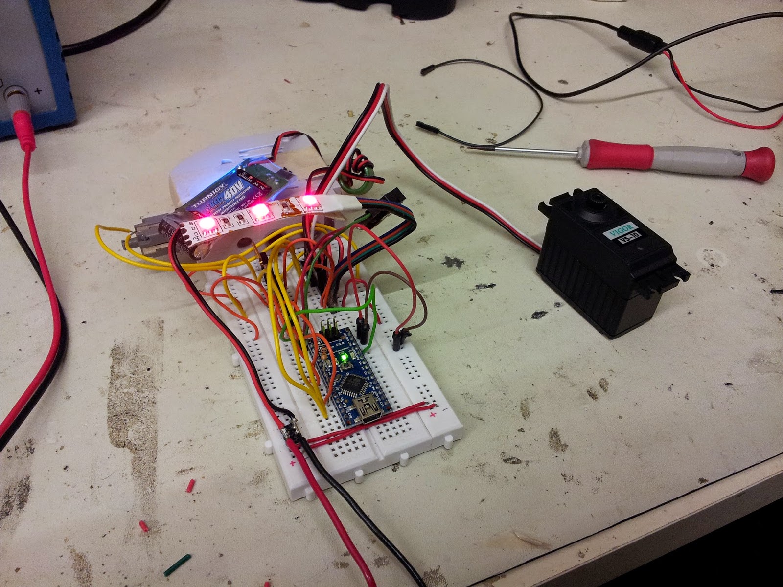
Colson Bot went together very quickly. I had only 8 holes to countersink and a few things to wire.
![]()
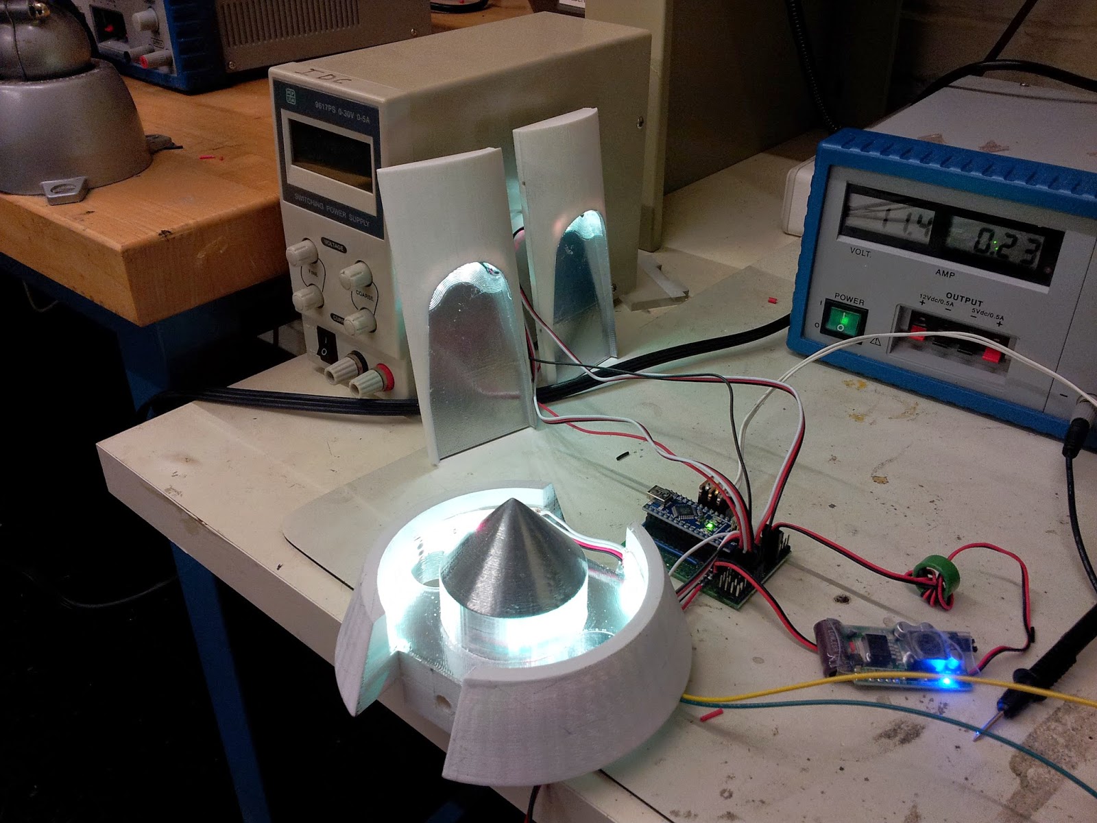
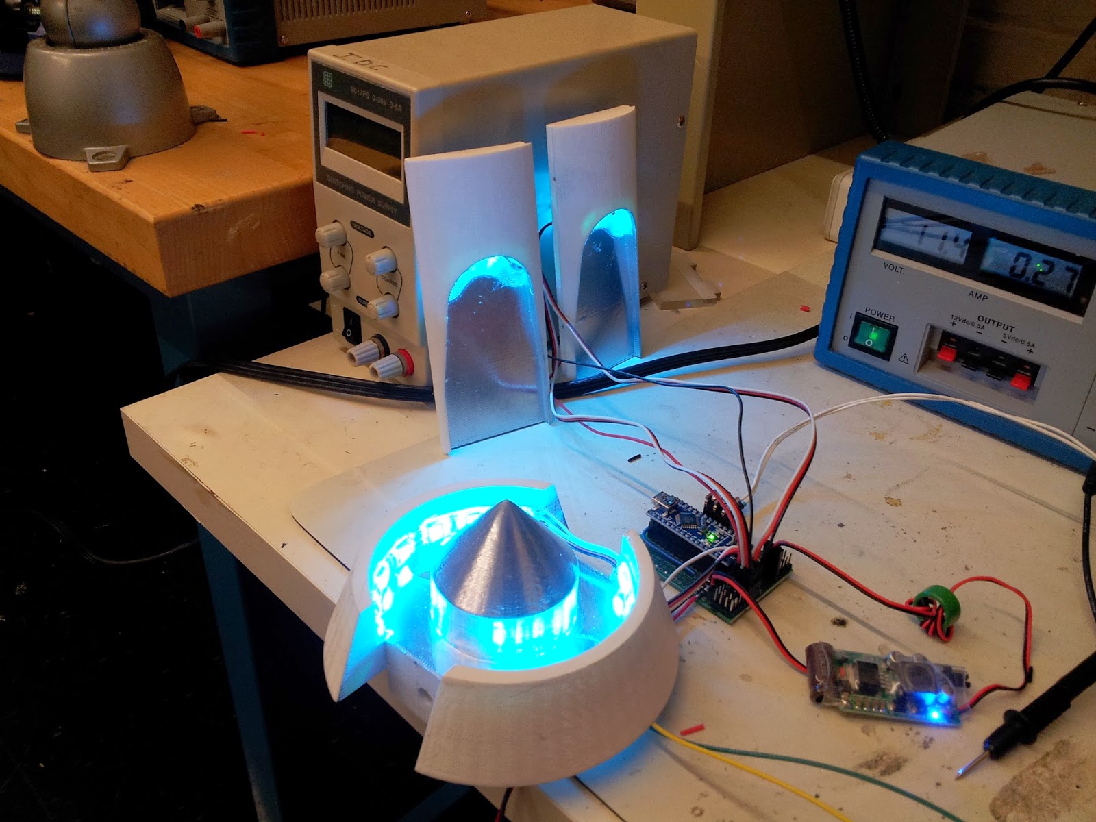
...and functionality tests.
![]()
![]()
![]()
![]()
![]()
Turns out the hotter wound motor is too fast. With the spring steel wedglets gripping the floor, I couldn't get enough ground speed to bite into the opponent. The first match shows robot milling while the second match shows more effective biting from 30% throttle.
The second match also shows why I should stop trying to push opponents into the pit. Fail.
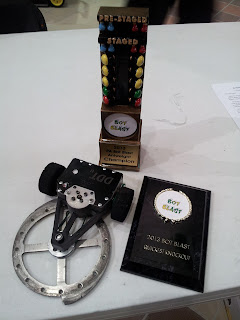
Colson bot did not receive the same recognition as I had expected because the EO was rushing. Here is the result.
Without an e-clip on the motor, the top comes off and splays itself around the arena.
As tradition, out entries must consist of several "assbots" among our serious entries.
Wheel! (Colson Bot)
After four years of being relatively invincible, I have decided to force-retire DDT. Replacing it at Dragon Con will be the beloved assbot dubbed "Colson Bot".
In the mid-2000's, the arena hazard for micro battles was a colson wheel attached to the output of an angle grinder. It was well known for its overpowering hits that often determined the outcome of the matches. Colson Bot was designed to look and function very similarly... without the stability of being bolted to the ground.
Being an assbot, I had determined that the budget would be minimal. Luckily I had just disassembled DDT and Prop Quiz which left me with several options for controllers and motors. I elected to recycle the gearmotors from Prop Quiz and the electronics from DDT.
There were two main steps to the design: finding a colson that could be bored large enough to fit the electronics and making a chassis small enough to fit in that bore. Given I had already selected my parts, I decided to reverse order design and build the chassis first.

Treads would have been ideal to maximize traction, but could not be done with the space constraint. Instead, the design used is pictured above. The robot is designed in layers. The bottom layer (including the wedge) is 3D printed out of PLA on one of the Invention Studio Ultimakers. The top section is waterjetted polycarbonate screwed on from the bottom of the robot. This top section mounts the Esskay 400xt brushless motor that directly drives the colson wheel (not pictured). I fully expect the 3D printed chassis to snap somewhere.
Colson Bot went together very quickly. I had only 8 holes to countersink and a few things to wire.
...and functionality tests.
Quick enough certainly. I'm dissatisfied with the acceleration of the robot, but once again I play the "apathy via assbot" rule. I have also yet to achieve maximum speed. the robot lifts off and goes unstable before I can spin it high enough. Although the esc braking function provides an interesting way to escape bad situations.
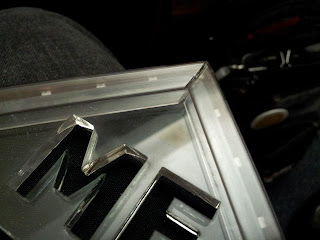
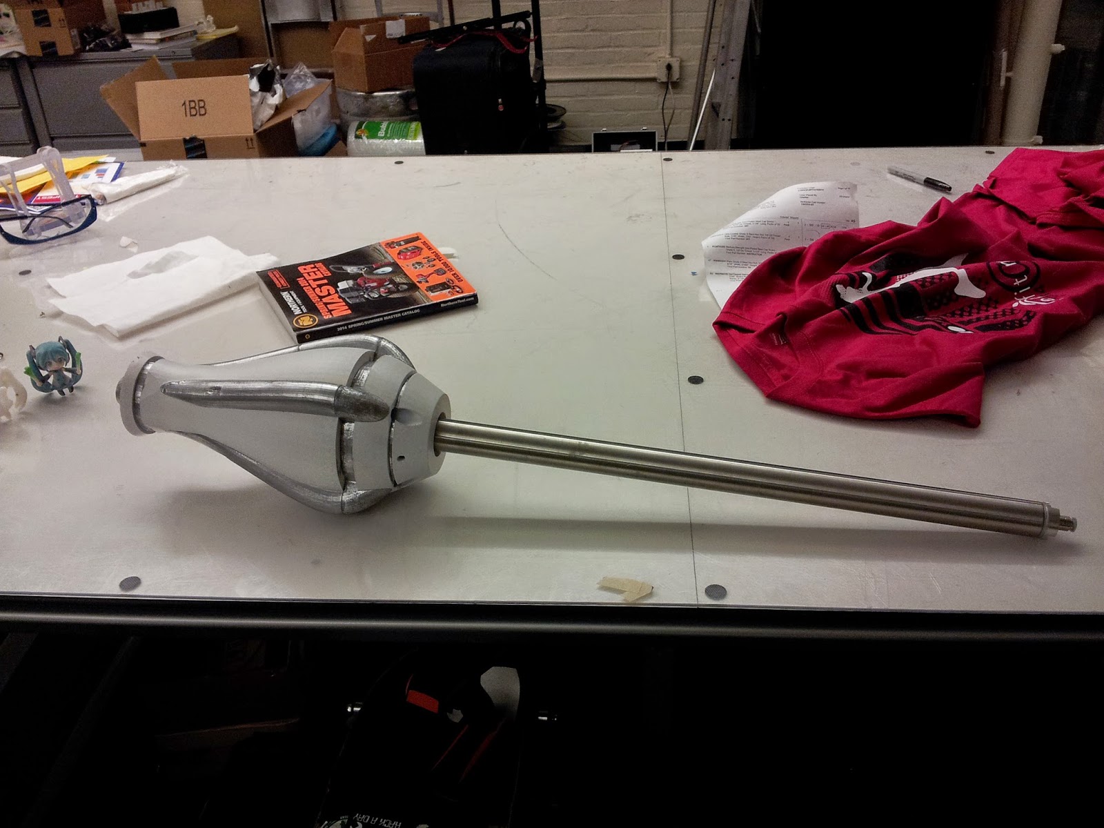
After a quick paint job, lets call it complete.
Dominant Mode
Clash of the Bots 3 showed me a few aspects of the robot that were not ideal:
- The unreliability of Spektrum technology
- The ineffectiveness of UHMW anti-wedge slips
- Something resulting in periodic signal loss
- Custom brushless drum subject to axial shifts
For now, we will waive off the Spektrum issue since it seem to have corrected itself somehow. The anti-wedge slips will be replaced by a few alternatives.
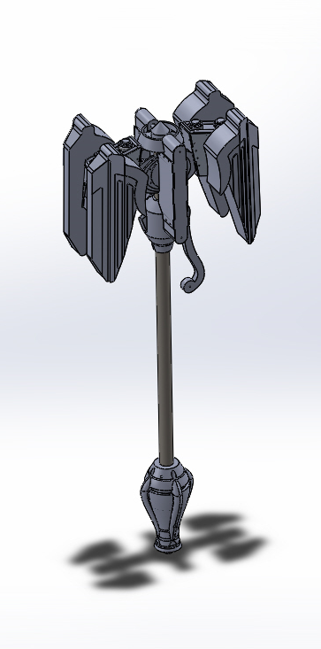
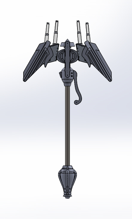
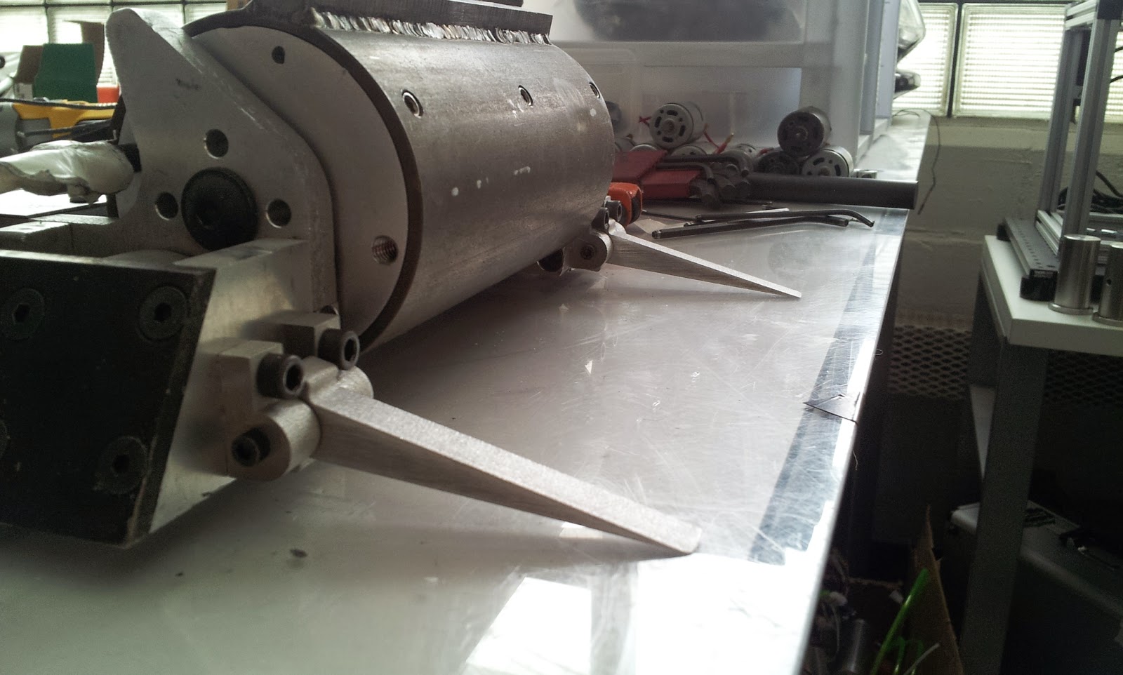
I drew up this design awhile back. It uses a set of Titanium forks to get under opponents. I favorite this design because it leaves nice sharp points to get under wedges and are not dependent on the position of the other wedge tips. This is a good feature to have in case part of the wedge incurs damage; the other fine points will not be affected.
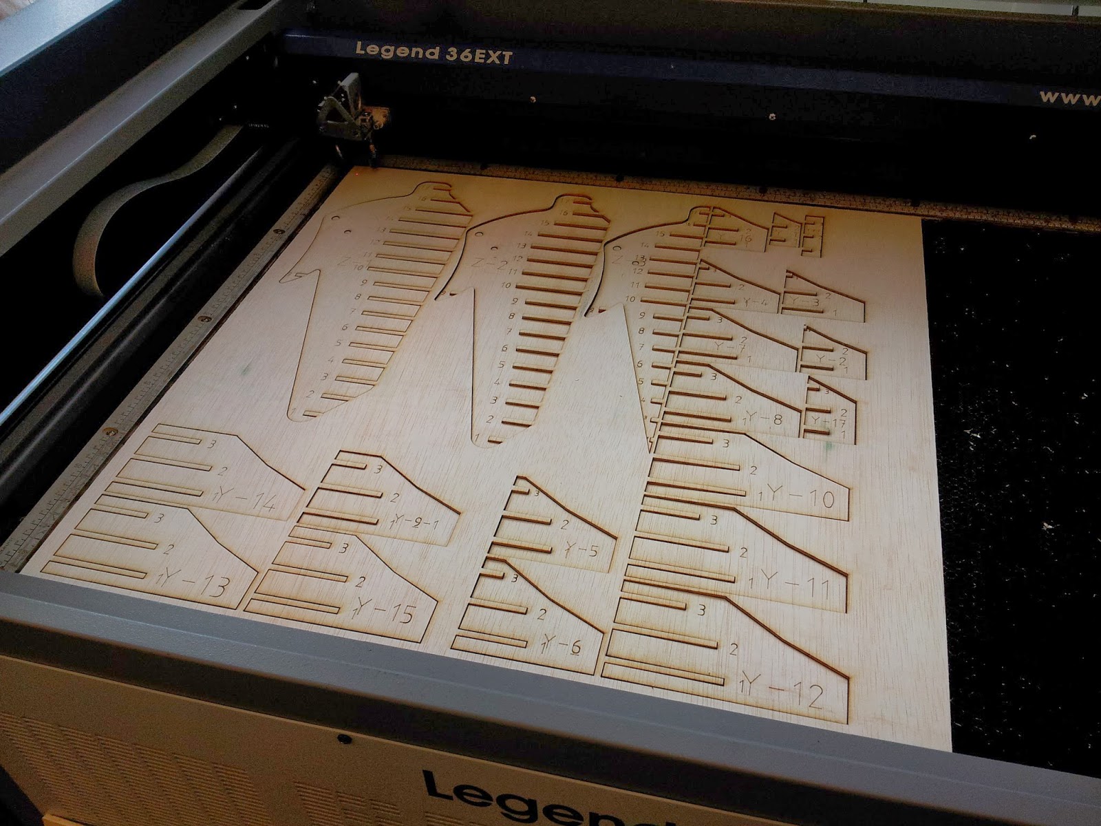
Others have recommended that I simply bend some blue-tempered spring steel. Since one option was clearly easier than other other, I decide to try waterjet machining some of the 0.01" spring steel stock I had bought for Razor Reloaded.
To prevent the drum shifting, I laser cut a thin ring of acrylic. This will keep the outer bearing from shifting off the mount. For Robot Battles, this should be fine as long as I don't fight and horizontal spinners. For future competitions, I will probably upgrade to a more ductile material like polycarbonate or polyethylene.
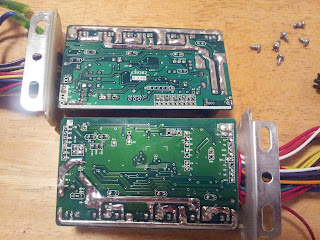
In previous experience with Cake, my first explanations to the radio cutoff was a short between the ground and +5V lines somewhere in the receiver. For Cake, this would usually occur around the drum shaft, where the drum shaft ID would eat through the insulation and contact the PWM wires. For Dominant Mode, no such symptom was to be seen since all the electronics were contained within the body this time. I though perhaps the motor windings were shorting somewhere again, but drive independent tests confirmed otherwise. What ended up being the concluded culprit was the receiver. I had Adam Bercu of Busted Nut Robotics pick up a Spektrum AR6115e on his way down to Atlanta, which solved the problems.
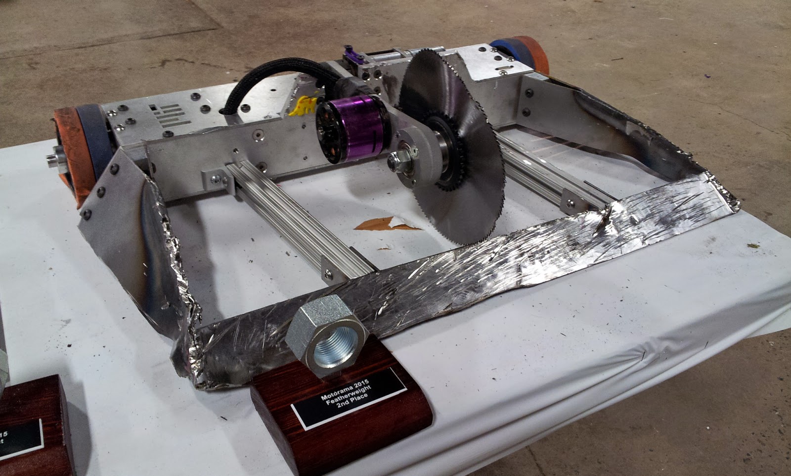
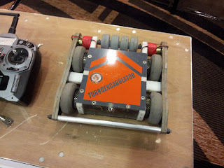
Turboencabulator
What in the world is a turboencabulator? Few people know, but it sounds pretty complicated even though the only new principle involved is power production from the modial interaction of magneto-reluctance and capacitive directance.
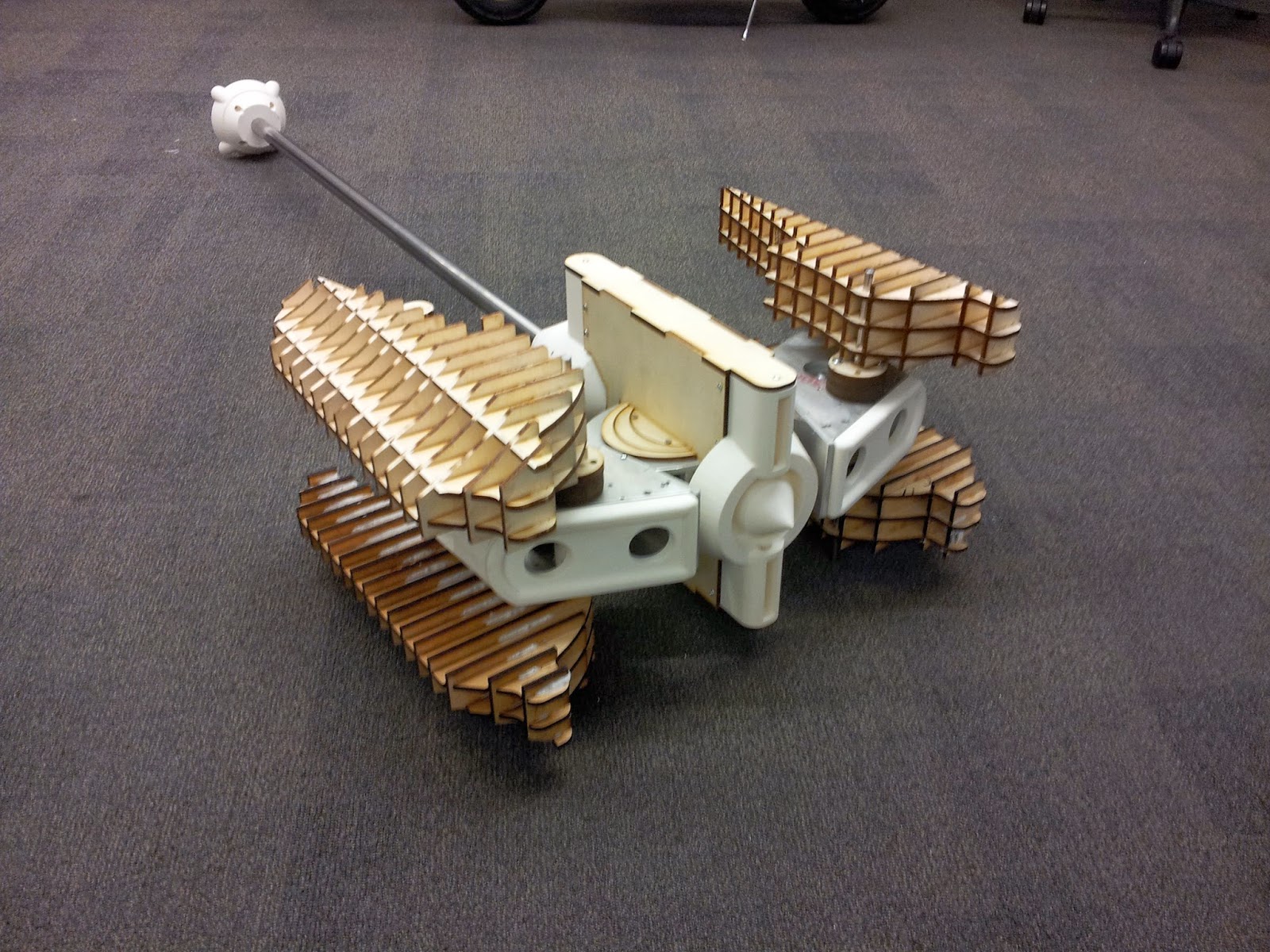
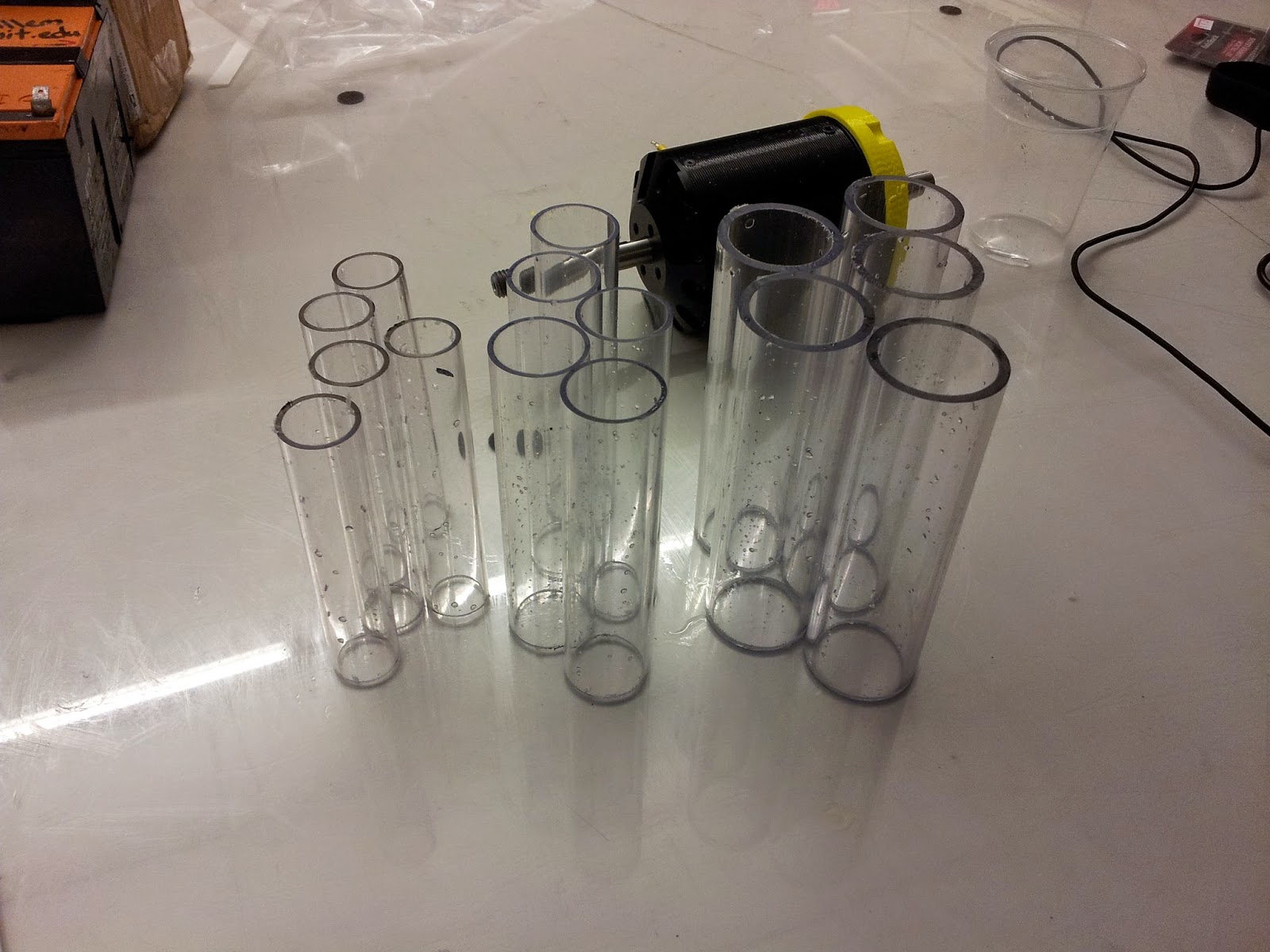
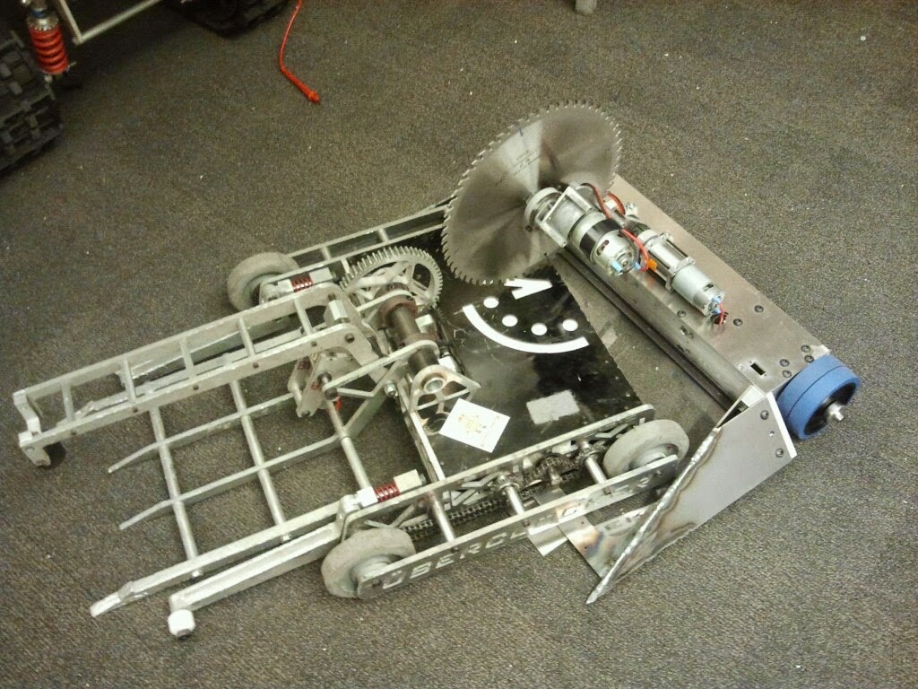
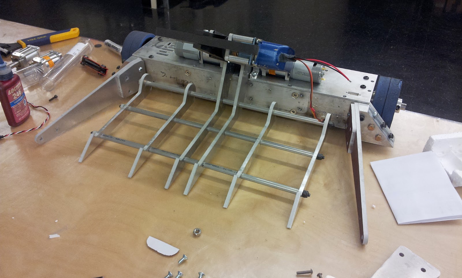
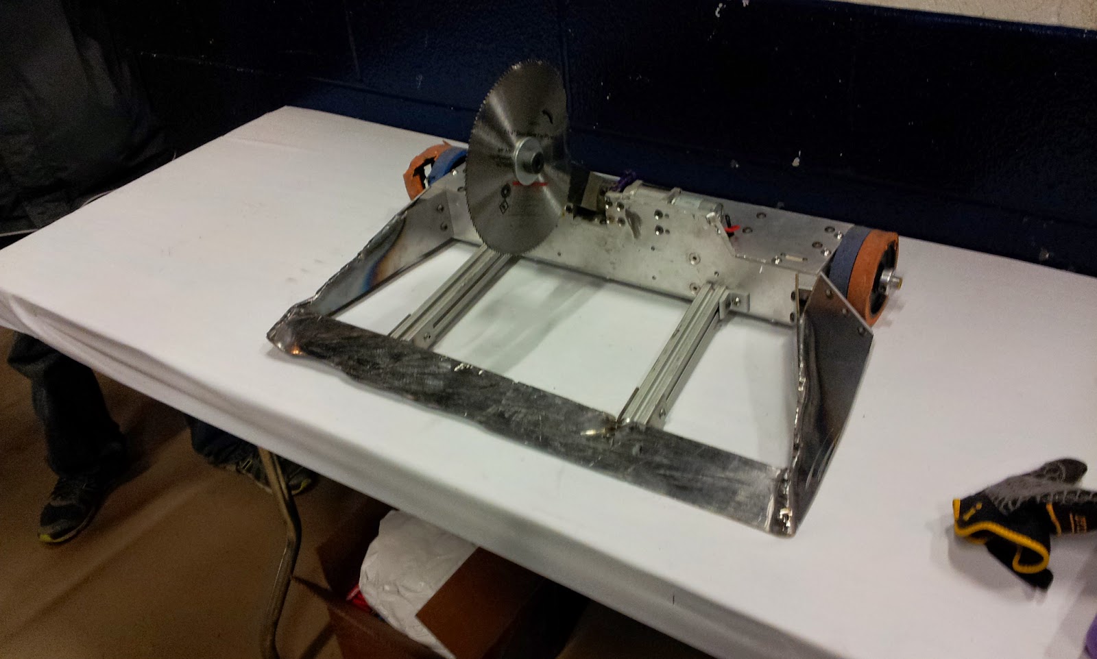
It is a sub-ass bot designed to go fast. I want it to be good yet require minimal spending on my part so many of the parts will be recycled from random things. The basic idea was to create a sturdy 4-wheel drive base and incorporate some simple active weapon on it.
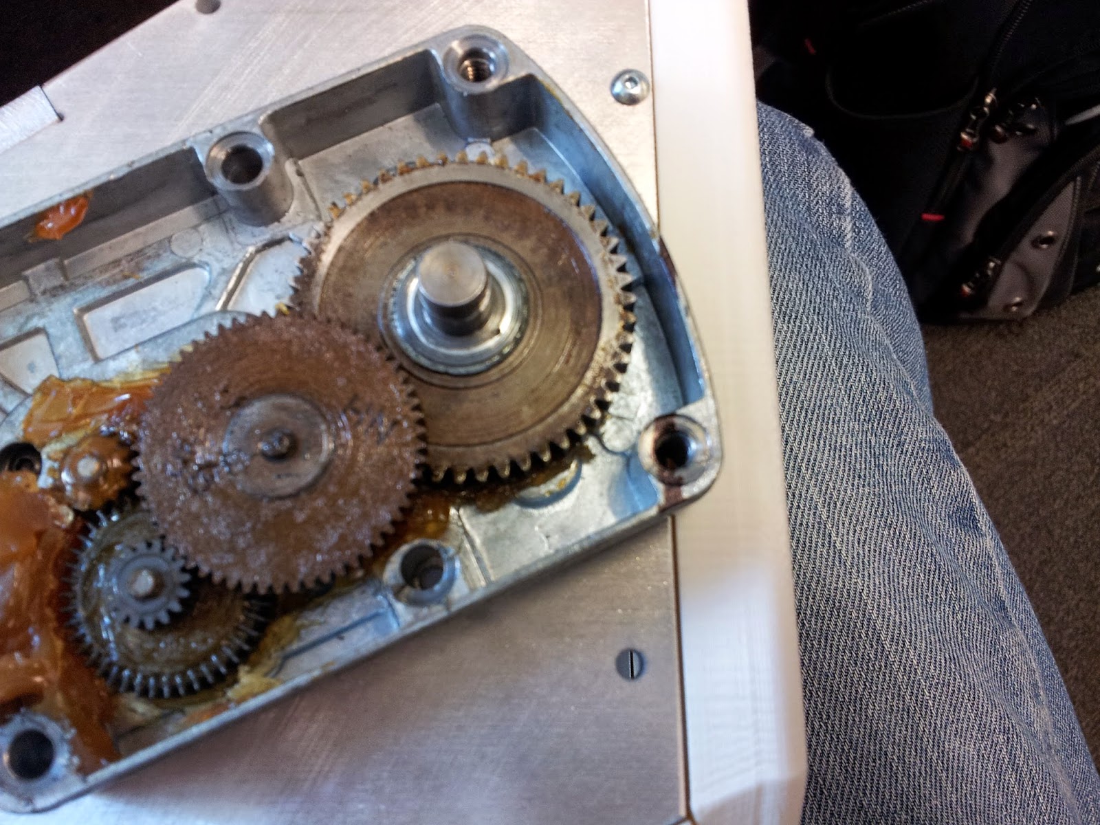
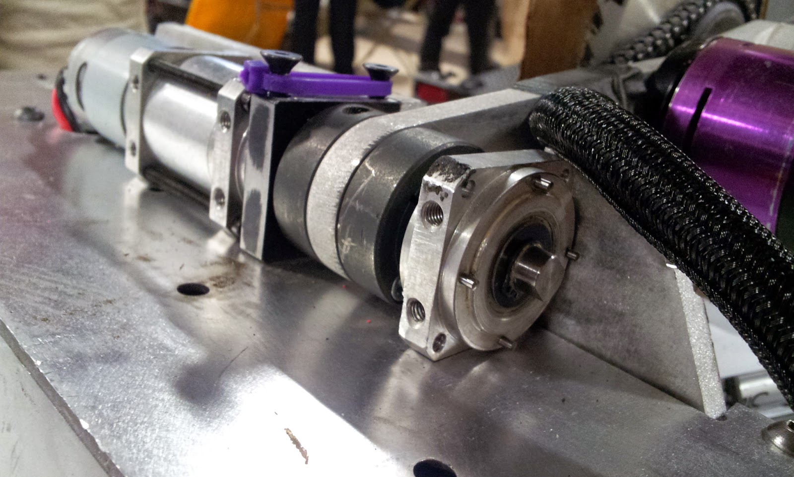
I was originally intending on using some 860-sized Johnson motors on some 5:1 gearboxes I had, but I would only be able to use two of them and 4-wheel drive with chain would have become costly very quickly. Instead I opted for some low RPM (high kt) 540-sized motors from surplus center. These guys put out a whopping 62 oz-in/amp! Combined with the 5:1 gearboxes on 3" wheels, I could move 24lbs while only drawing 16 Amps continuous. Sounded like an ideal duty for my Banebots 12-45 ESCs that havent seen action since 2008.

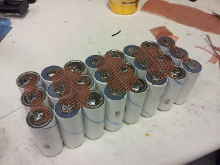
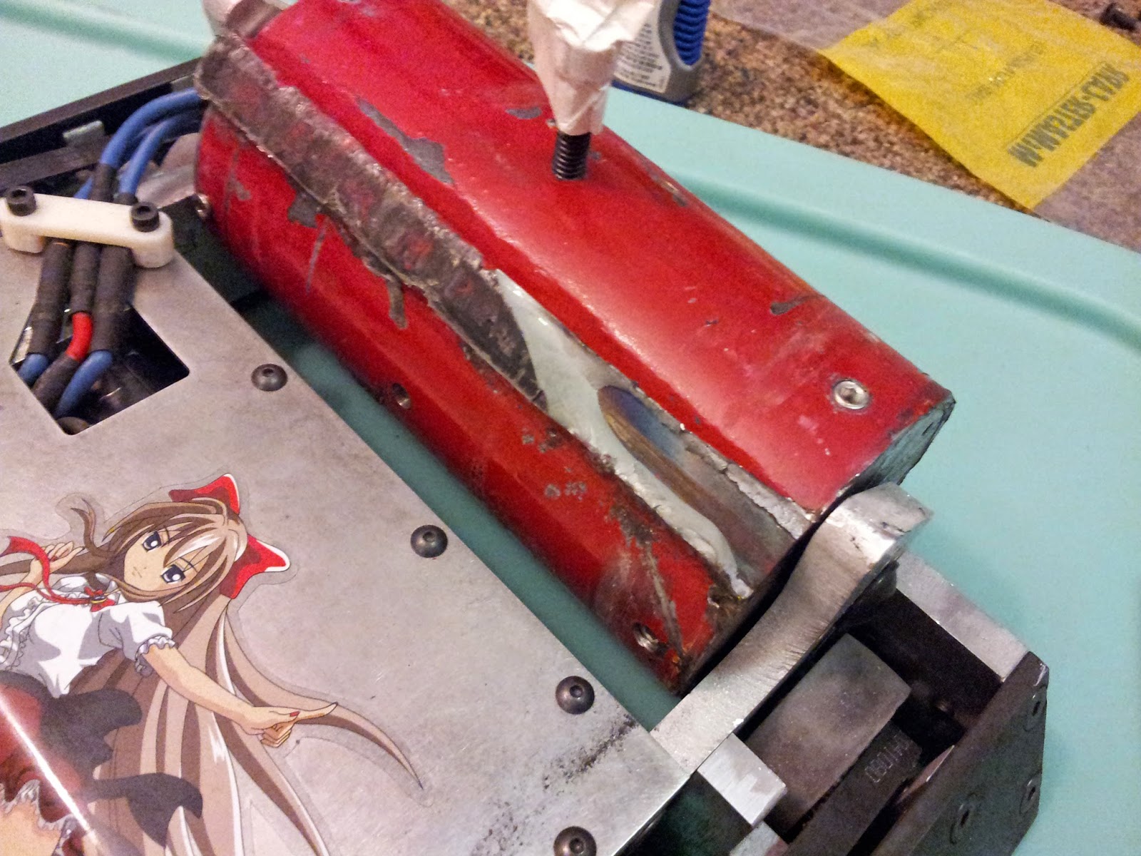
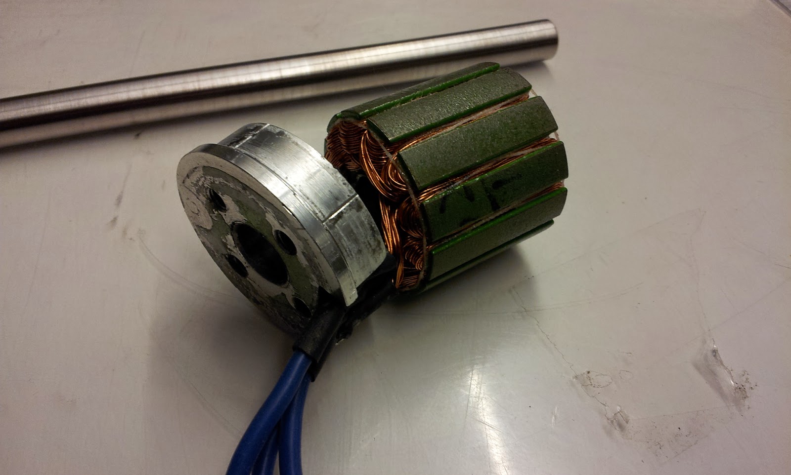
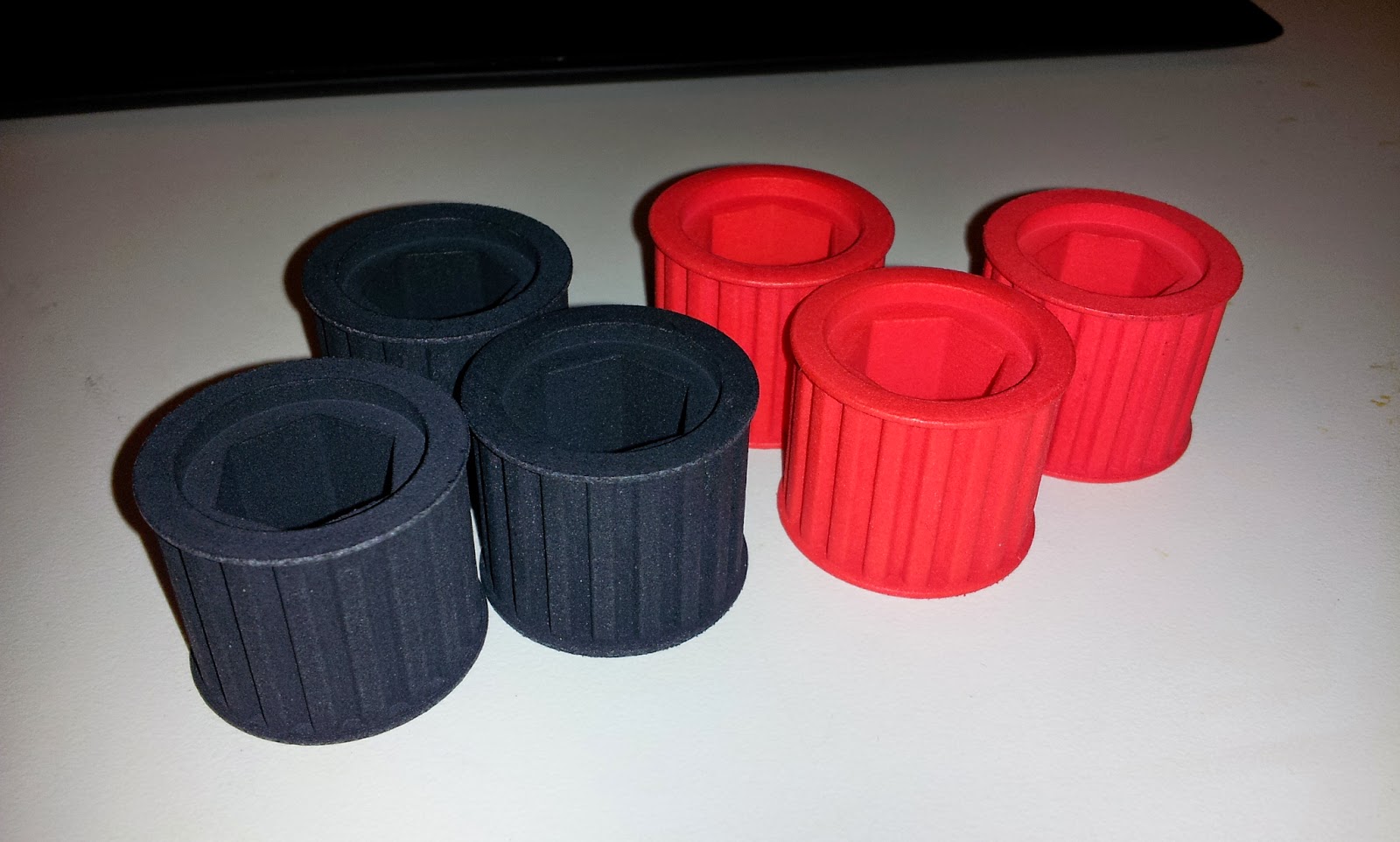
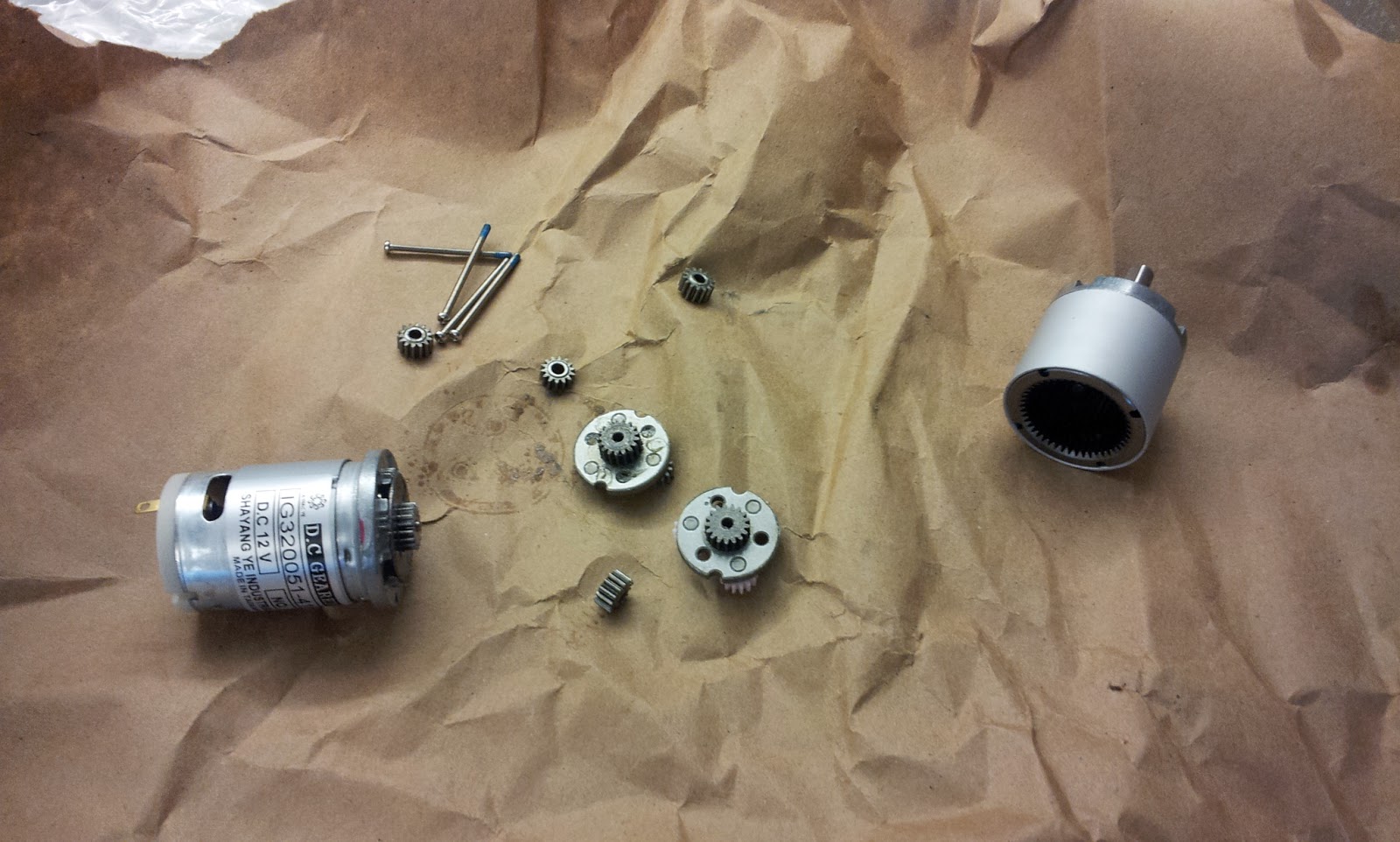
The 5:1 gearboxes were salvaged from the Hitachi copier motors that we previously purchased for stator grabs. We had maybe 6-7 of them on hand and since they included bearings it was idea for a low cost solution. Pinions were made from the motor-side shafting by rough cutting them to length, facing them, and then boring them on the lathe. The arbor press finished the installation process.

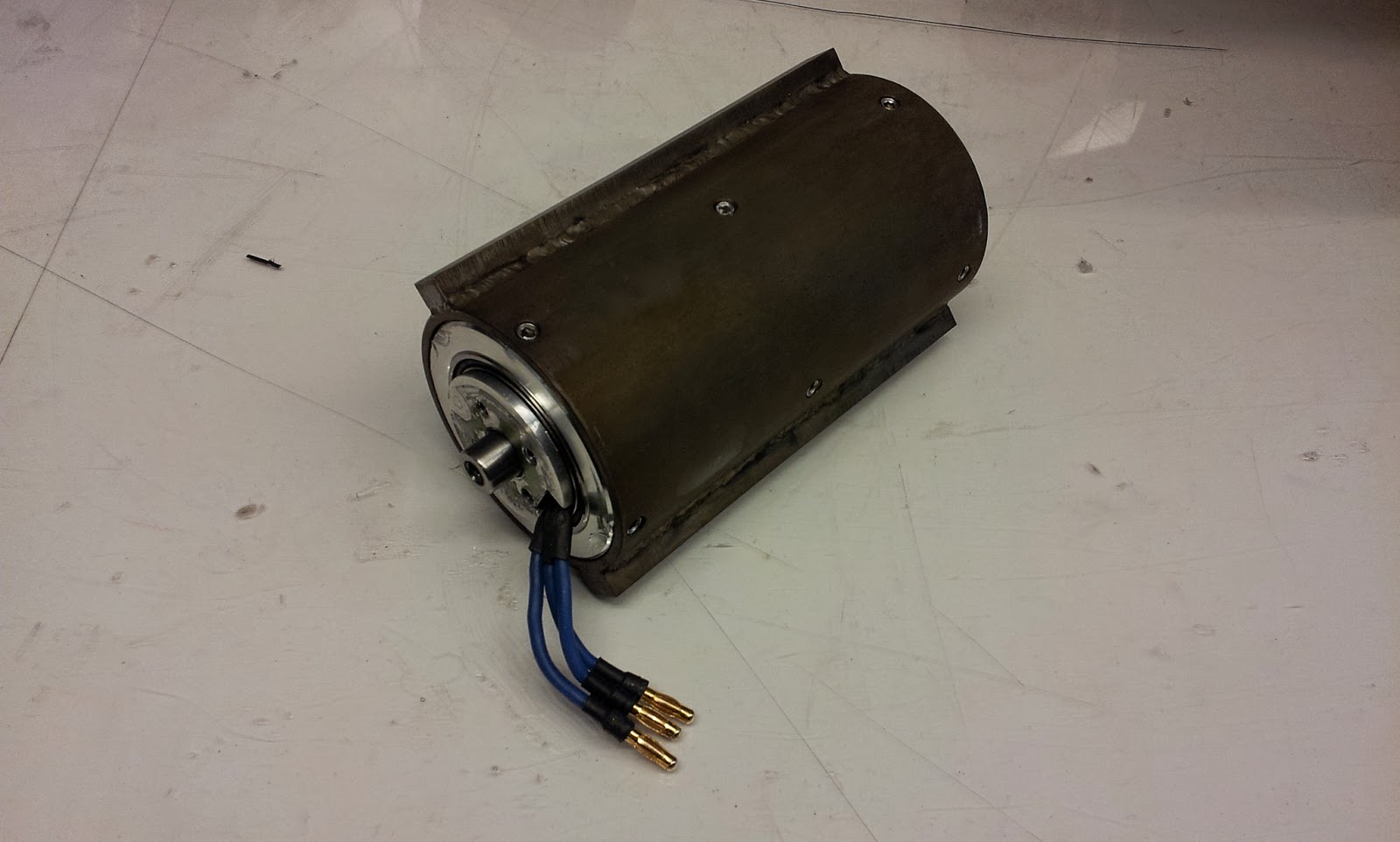
The 30A Mcmaster bots wheels were pressed directly on the shaft of the output gears. This assembly was suspended in between two frame rails made of HDPE (for now).

From there, the robot quickly went together.
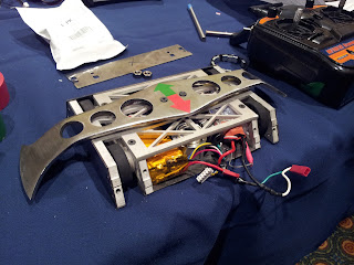
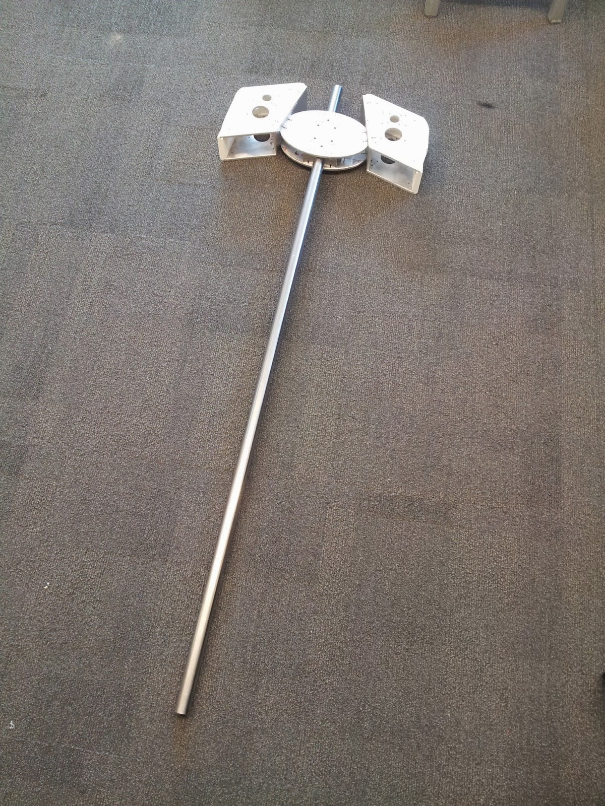
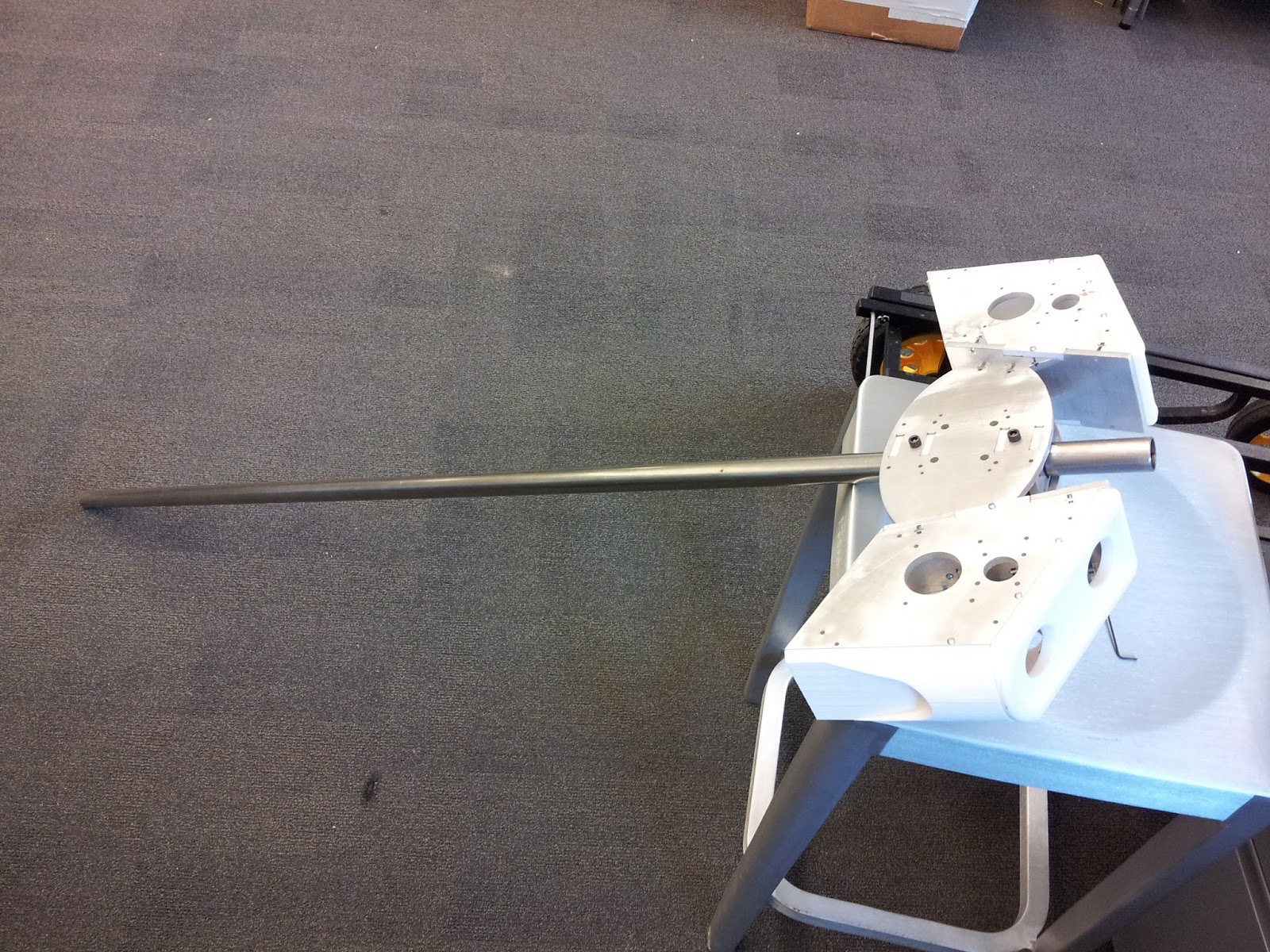
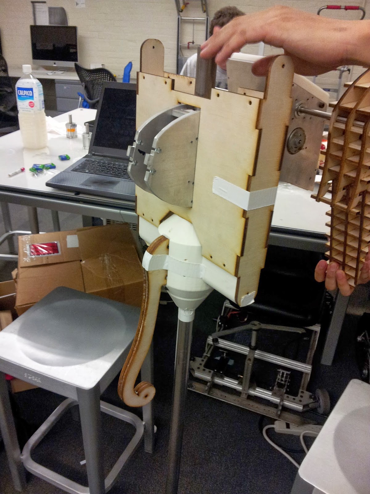
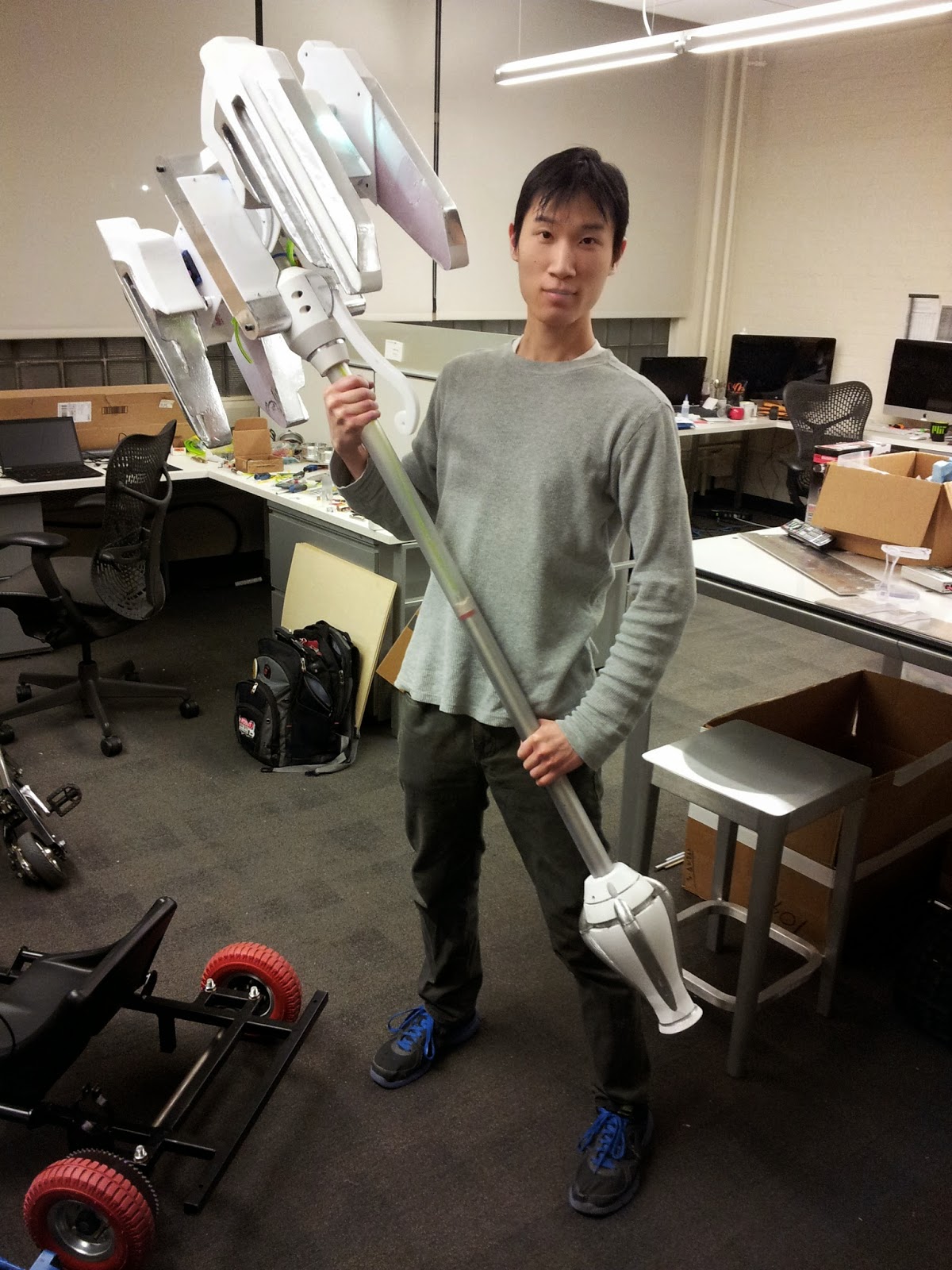
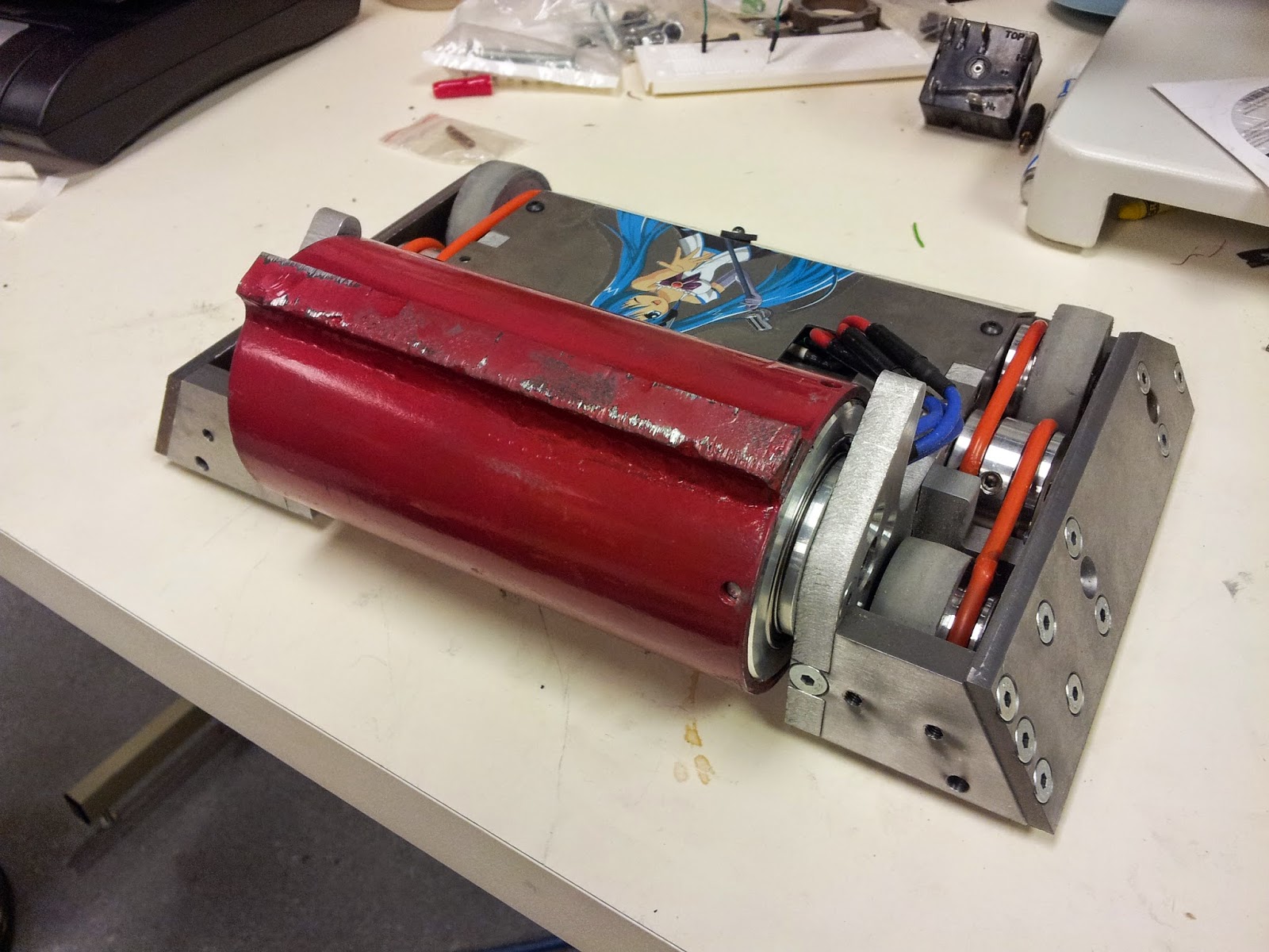
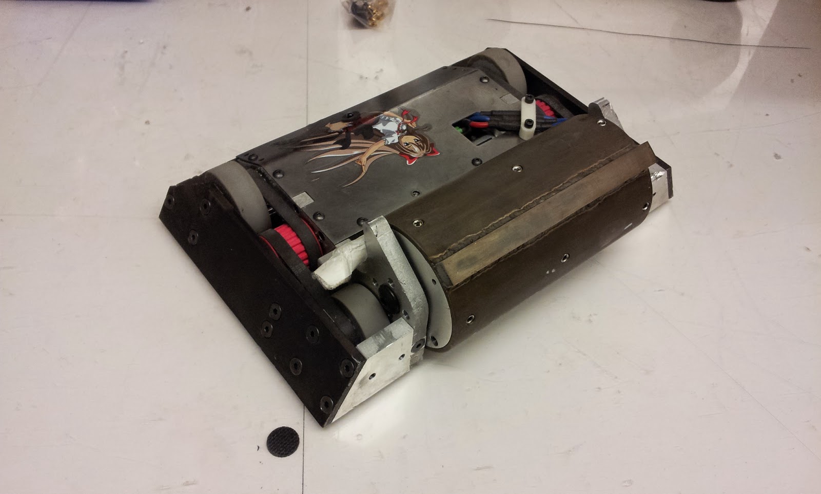
 |
| The Turboencabulator sans roller weapon. |
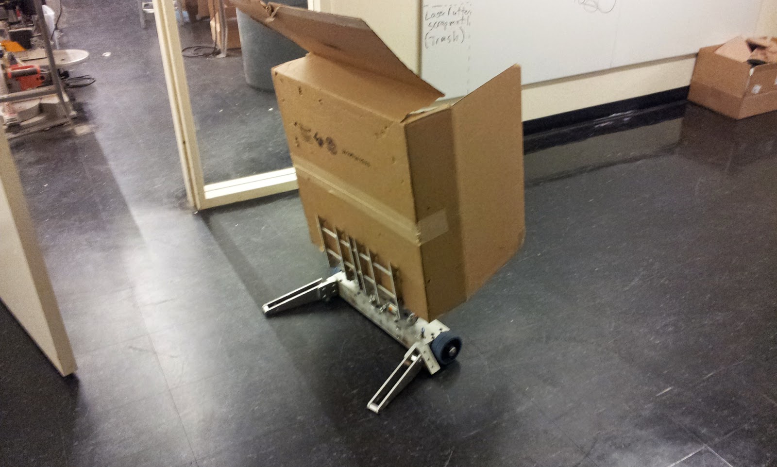
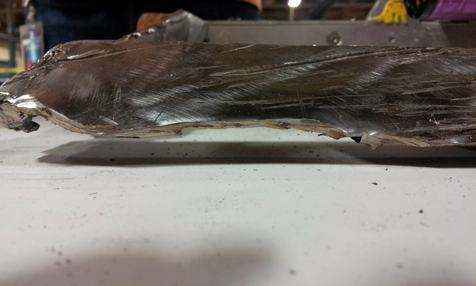
However, did not fair well in some sparring.
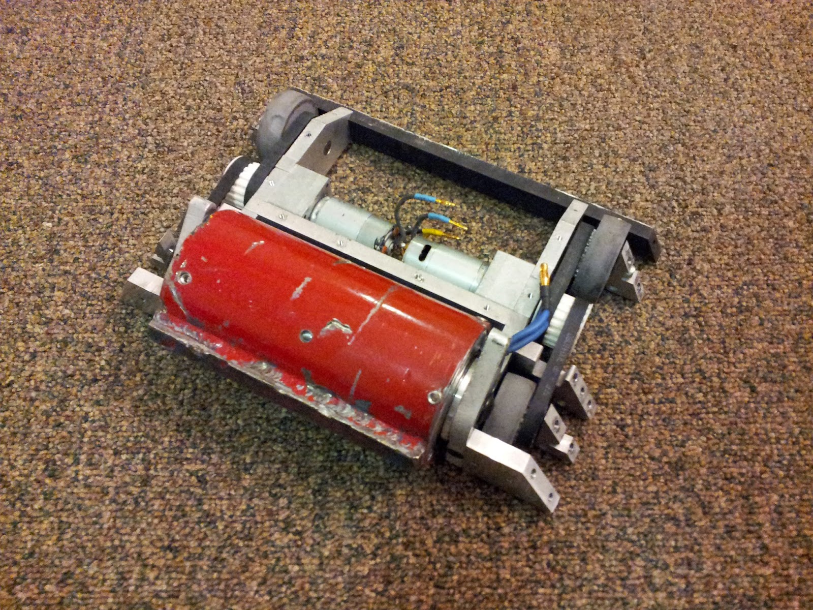
 |
| The Carly Rae Jepsen Wallbanger puts a nice one into Turbo's side. |
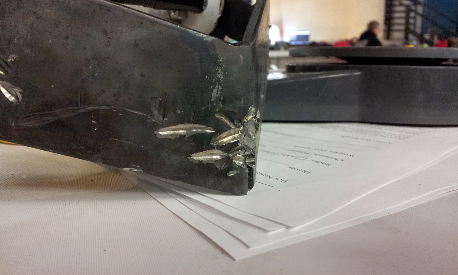
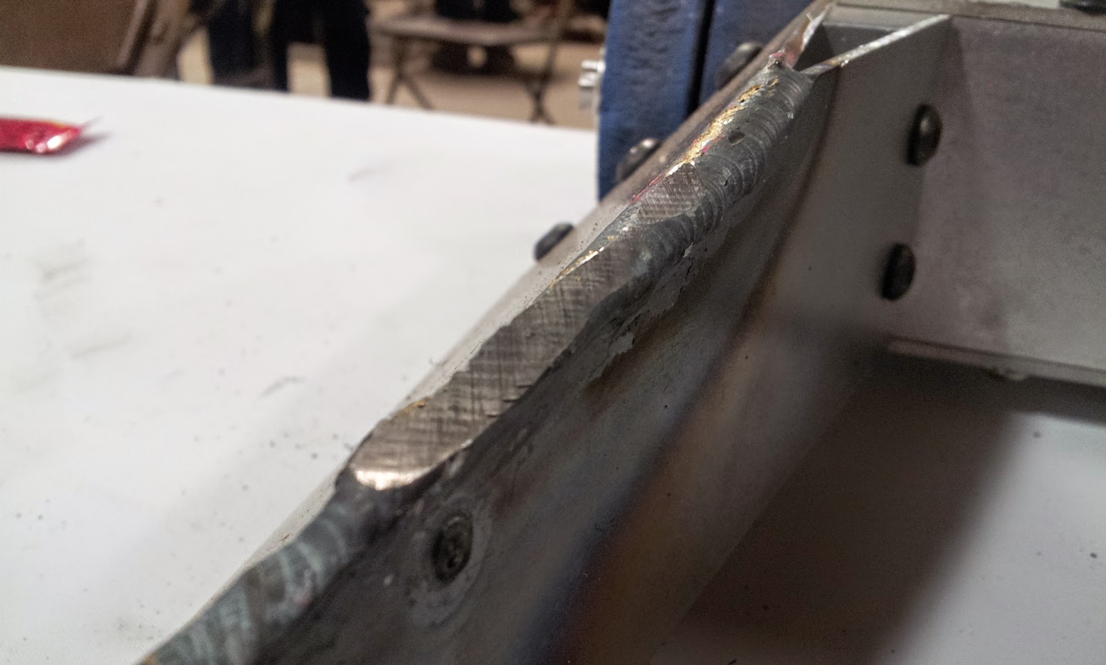
The hit actually smashed in a roller motor and deformed the HDPE enough to cause plastic deformation. So the robot was upgraded with steel outer panels thanks to Adam once again.
Intermisssion: Other happenings during the Dragon Con prop week.
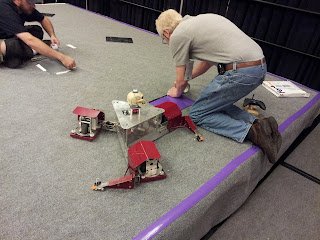
Fun things to do with 30 pound combat robots:
 |
| The MIT crew bought over 14 power tools from Harbor Freight to hack into robot drives. |
 |
| Greg bot (Critical Space Item). It has the drive train of a 12 pound robot. |
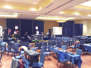
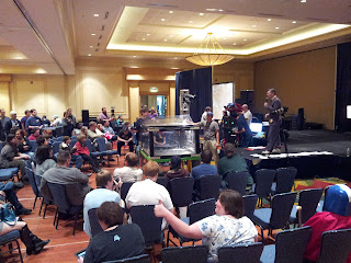
Competition: Sunday
There wasn't much to say about Micro battles because the competition did not last long. It was originally a double elimination tournament but due to the record number of competitors and truncated time allotment for the ballroom, they decided to switch tournament types mid-way through.
Dominant had only one opponent before driving through the pit. Here is the footage.
Turns out the hotter wound motor is too fast. With the spring steel wedglets gripping the floor, I couldn't get enough ground speed to bite into the opponent. The first match shows robot milling while the second match shows more effective biting from 30% throttle.
The second match also shows why I should stop trying to push opponents into the pit. Fail.
Colson bot did not receive the same recognition as I had expected because the EO was rushing. Here is the result.
Without an e-clip on the motor, the top comes off and splays itself around the arena.
Competition: Monday
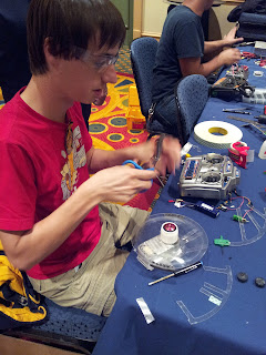
Arrived nice and early to talk jabber with the other builders.
![]()
Arrived nice and early to talk jabber with the other builders.
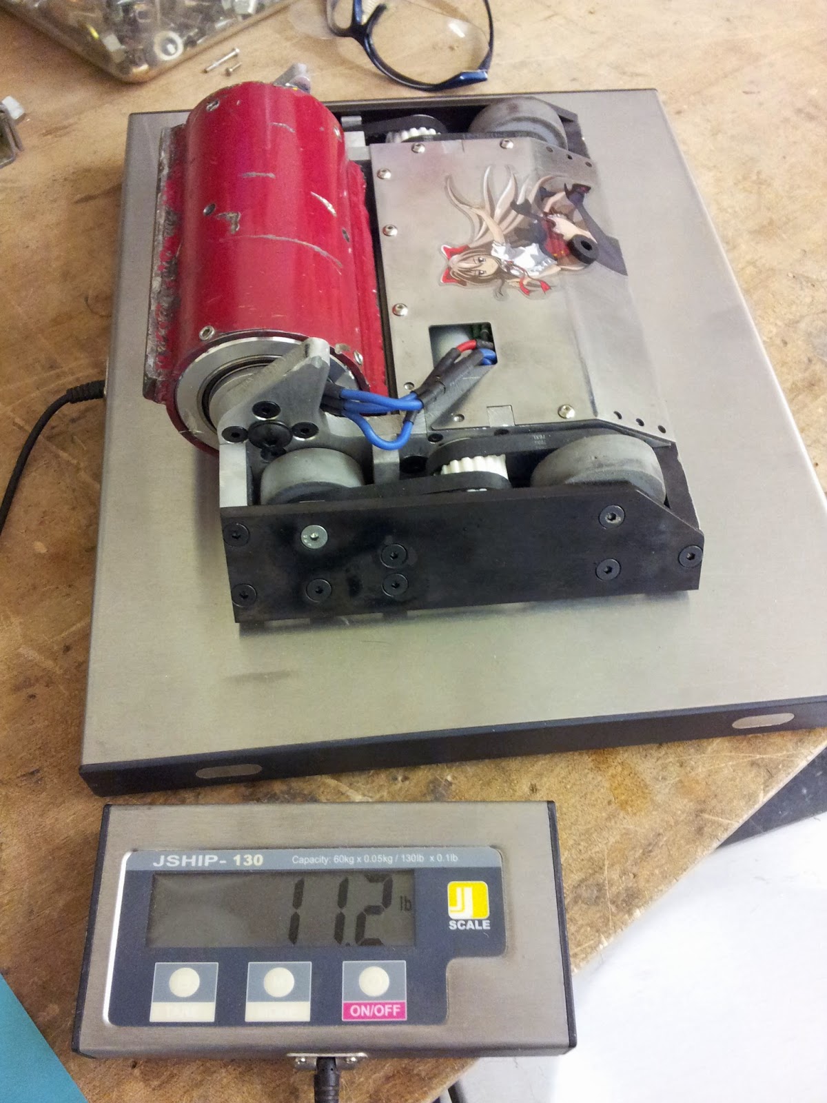
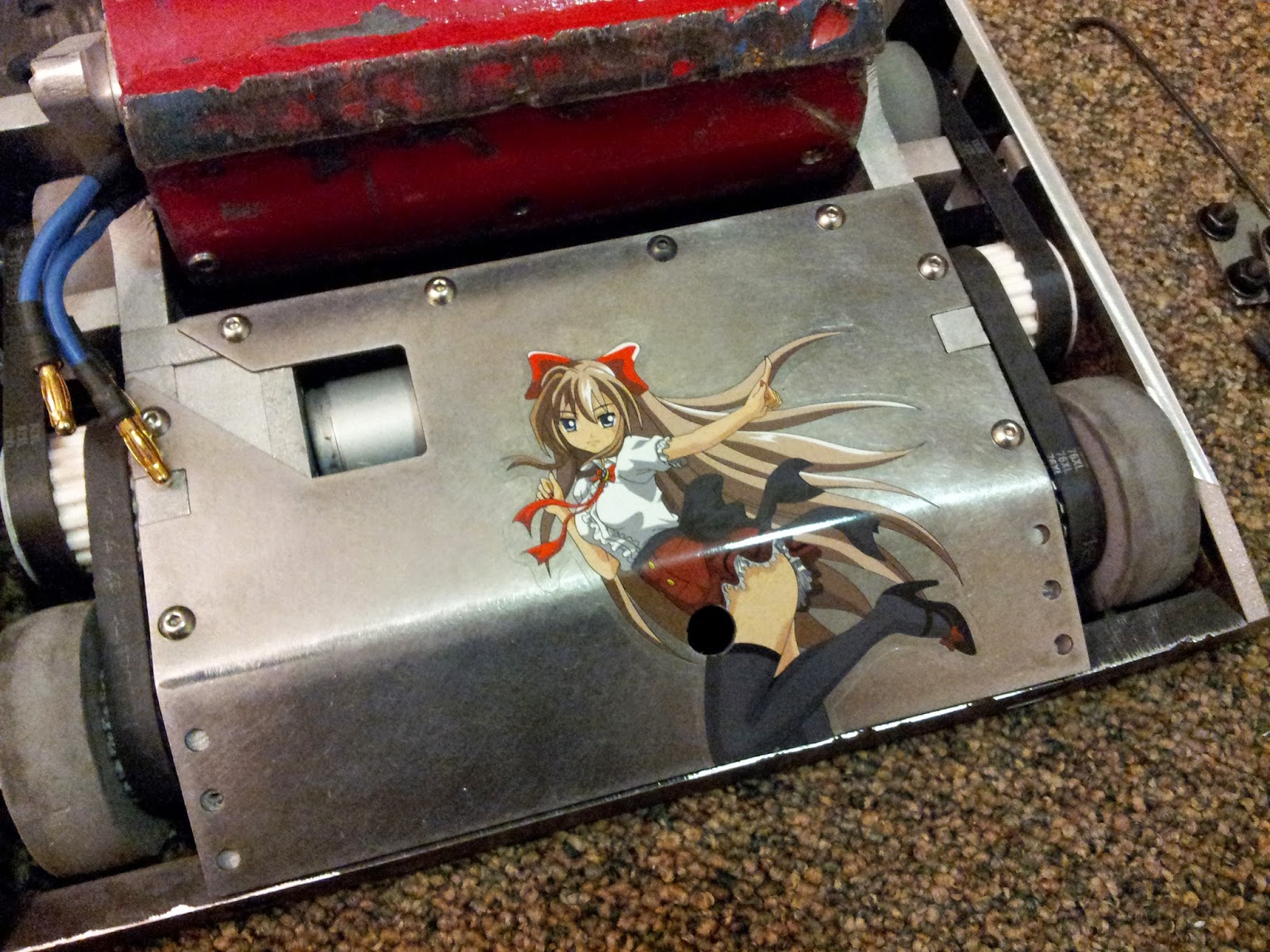
Turbo was ready to go, fully charged and sporting its new A-36 side plates. It weighed 11.5 lbs.
![]()
![]()
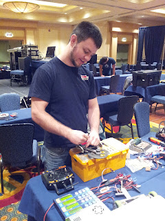
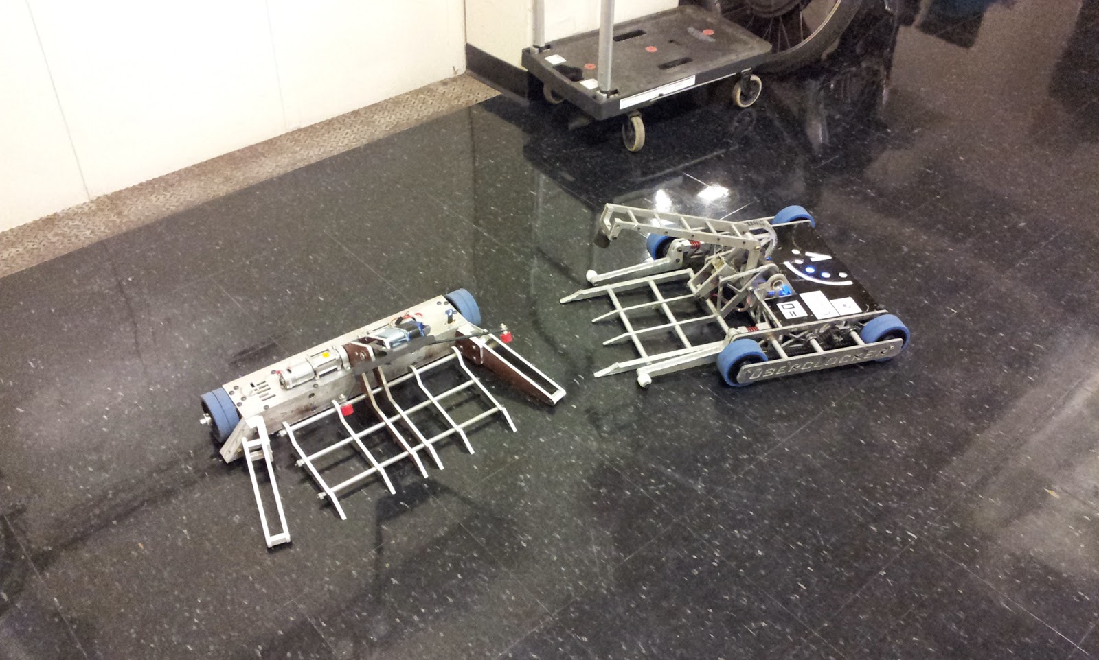
Our friends from the north were already there with a beautiful array of 30 pound robots.
![]()
Dale Heatherington brought the competition's first fully autonomous robot, Scary-Go-Round. It is able to track the opponent and stage boundaries while constantly rotating. Quite an amazing robot.
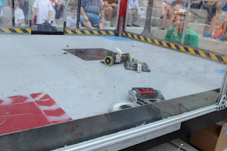
Turbo had the first match of the competition against a solid block robot named Ice Cube.
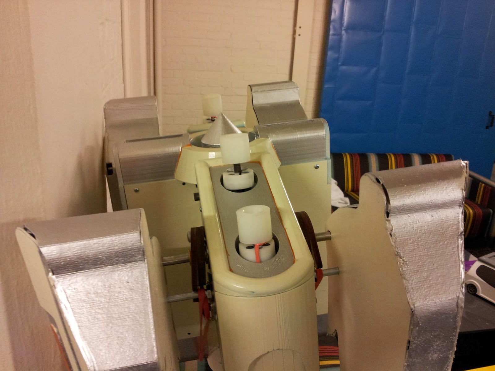
The rollers worked perfectly! Between the higher RPM 2" colsons and the 3" mcmaster bot wheels for drive, I was able to "dribble" my opponent on top of my robot for the perfect delivery. Match 1-3 was a great display of control over the opponent.
Unfortunately, match 2 was not as lucky. I was pitted against a robot named Tilla the Hun, which used a very similar principle to turn over other bots.
He had wire brushes for wheels which gave him superior traction on the carpeted surface. I though perhaps my ramming mass alone could push him back but he had superior traction.
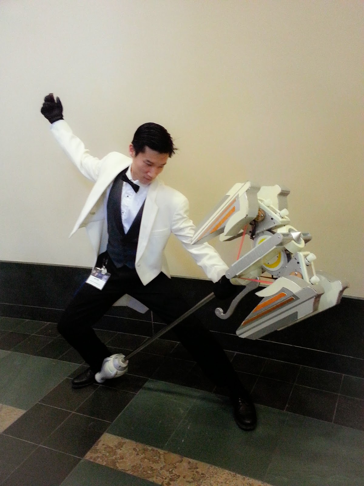
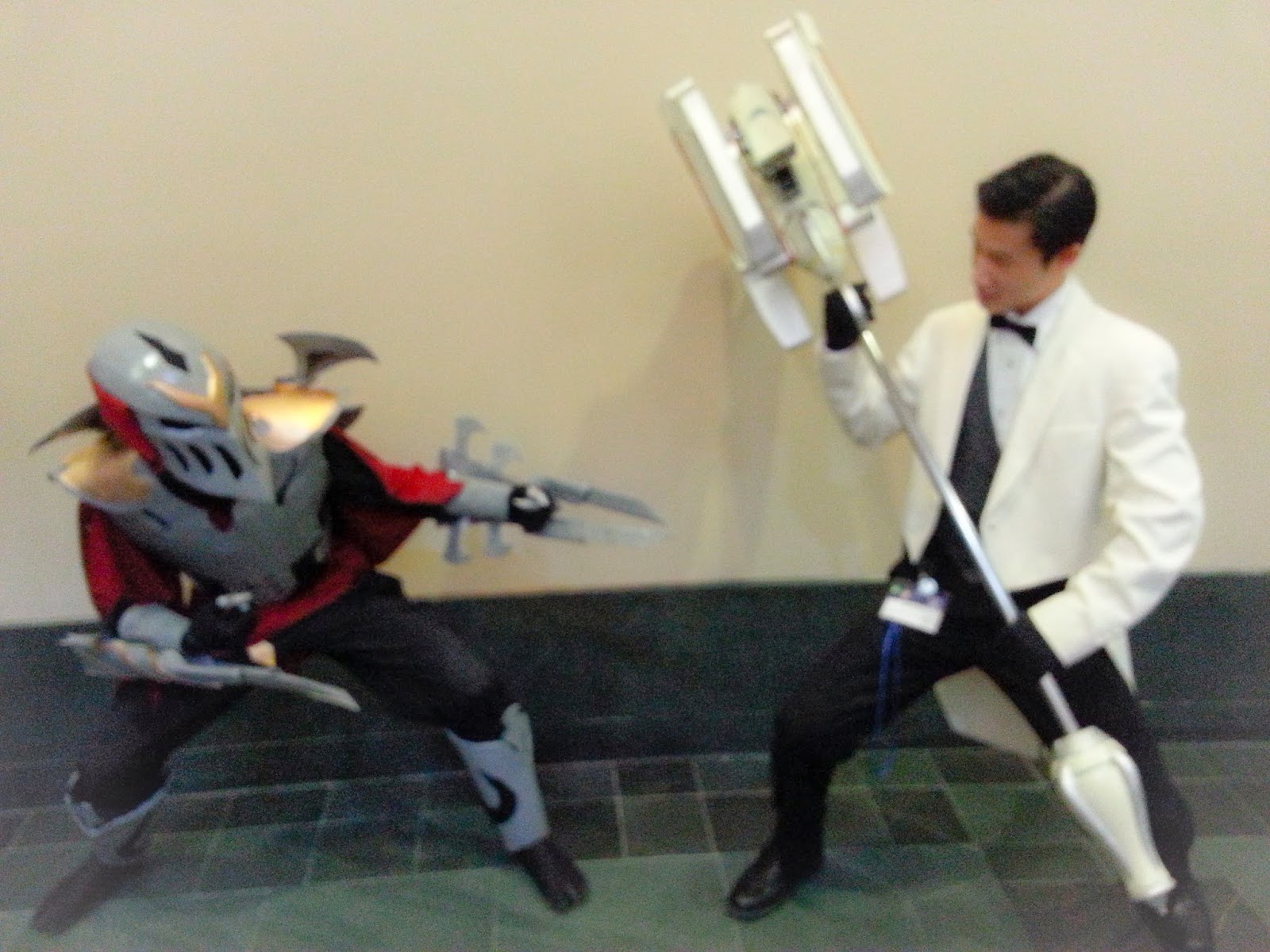
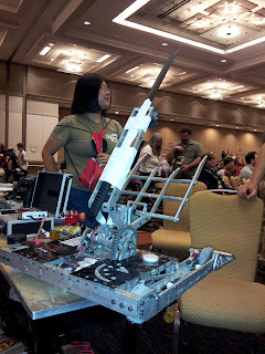
For the rest of the competition, I aided with Charles' and Adam's robots since they had some major repairs between matches. One of which resulted in Uberclocker Ubershanker.
![]()
That is my $15 katana strapped to the clamping arm of Uberclocker to try and compensate for its broken lifter spatula. It actually worked vs a match against Pinball, as it lodged perfectly in between the body and top plate.
Turbo's final appearance was in the 12 pound rumble where it once again showed its ability. Because Michael Jeffries of Near Chaos Robotics swept both events, I was gunning for him but Apollyon's quick drive train kept it a chase the entire time.
Conculsions


Our friends from the north were already there with a beautiful array of 30 pound robots.
Dale Heatherington brought the competition's first fully autonomous robot, Scary-Go-Round. It is able to track the opponent and stage boundaries while constantly rotating. Quite an amazing robot.
Turbo had the first match of the competition against a solid block robot named Ice Cube.
The rollers worked perfectly! Between the higher RPM 2" colsons and the 3" mcmaster bot wheels for drive, I was able to "dribble" my opponent on top of my robot for the perfect delivery. Match 1-3 was a great display of control over the opponent.
Unfortunately, match 2 was not as lucky. I was pitted against a robot named Tilla the Hun, which used a very similar principle to turn over other bots.
He had wire brushes for wheels which gave him superior traction on the carpeted surface. I though perhaps my ramming mass alone could push him back but he had superior traction.
For the rest of the competition, I aided with Charles' and Adam's robots since they had some major repairs between matches. One of which resulted in Uberclocker Ubershanker.
That is my $15 katana strapped to the clamping arm of Uberclocker to try and compensate for its broken lifter spatula. It actually worked vs a match against Pinball, as it lodged perfectly in between the body and top plate.
Turbo's final appearance was in the 12 pound rumble where it once again showed its ability. Because Michael Jeffries of Near Chaos Robotics swept both events, I was gunning for him but Apollyon's quick drive train kept it a chase the entire time.
Conculsions
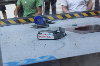
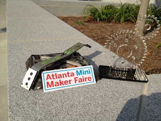
Overall, the competition was a personal fail considering my experience but it was a nice change of pace. I was able to experience the relaxing end of robot combat with the best seats in the house (backstage). I'll be thinking about new designs for future competitions. The next competition believe is the Atlanta Mini Maker Faire (October 6th) and Chattanooga Robot Battles.
I'm dreaming of a 12-pound Uberclocker...
I'm dreaming of a 12-pound Uberclocker...
.jpg)