Quantcast
Viewing all 48 articles
Browse latest View live

Textual Updates

It is a loosely kept secret that I am not currently residing in Florida or Georgia this summer. As a result, summer term creativity has been pretty mute.

Some might call it slacking. I've reacquainted myself with Team Fortress 2 and all the hat(in)sanity. I've also been experimenting with this new Google+ object. Both of which I am proud to say, I HAD IT BEFORE IT BECAME FREE.

Anyway, I've not been slacking. PA Bot Blast will happen this upcoming Saturday and my robots have been ready since April. Each one of them snuggled in their little bubble wrap blankets, suffocated in duct tape. It is time to check on them.

This week I will begin cycling batteries and practice driving. I am confident each robot will put on a spectacular show, but by no means will this be an easy competition. If you are in the PA area, I encourage you to visit the event in Bloomsburg, PA.

http://www.buildersdb.com/eventdetail.asp?eventid=334

In other news, OTAKON! I've registered for an anime convention I felt like attending and so preparations begin! I had Irony Man shipped up to my location so I can work on him. Upgrades are expected. I'll be using a arduino mini instead of the Duemilanove for size and simplicity of power routing (since I can run the mini off 3.3V, and hence require only one cell). I'll also be running some Luxeon super bright LEDs instead of the current modules.

Yeah.

Last Week and Next Week (PA Bot Blast and Otakon)

Finally, a weekend where I am not rushing about to see new places or compete against other sentient beings. However I have stuffs to prepare for next week so after 7 hours of straight soldering, I elect to type up a post while I am still on a solder fume high (no not really).

Made the drive from Maryland to Pennsylvania for my first ever PA Bot Blast event! Driving up to Harrisburg in the wee hours of the morning but when I started up the road to Bloomsburg things sudden looked very hilly and untouched. Towns built into the valleys of the massive hills, which were covered with trees; to be honest I felt like I was in a northeastern Costa Rica. 7 halves hours later I arrived at the Columbia Mall and prepared to set up.

I brought P150, DDT, and Cake to represent the south. I hadn't really run these robots since April, so I assumed they were in working order. Boy was I in for disappointment. P150 and DDT both went 1W:2L for seemingly dumb reasons. They both lost wheels in their first matches. P150's was removed by hedgehog's angled cutter (and P150's poor control), and DDT's seem to have fallen off by chance (when Fangus and DDT hit, he popped the belt off the pulley, jamming the blade and spinning the robot, which threw the wheel off. If Fangus was the cause, my shaft would be missing). They then proceeded to defeat robots in their expected fashion only to lose again disappointingly. Some additional thought needs to be put into these robots.

Cake made a wonderful representation! 4 wins and 2 losses, both losses caused by One Fierce Lawn Boy from Fierce Robots. Every match ending up in KO. Videos below.


The money shot of the event. The final hit between Ripto and Cake in the loser's finals match resulted in Ripto being lodged between the lexan and the outer barrier. Ouch.


Jeremy ran a very professional event. Organized procedures, match listings, and even had clarifications for the grey areas of robotic combat. Needless to say, I'll be returning if I am in the area again!

PA Bot Blast 2011 Album


Image may be NSFW.
Clik here to view.

Next week will be Otakon, the largely anime convention in the Baltimore area. Now, I am not a huge fan of anime, but I do like to create. I had my Tony Stark, Iron Man costume shipped up to me during Independence Day break so I could work on it. A few upgrades ensued.

First I decided to add a blue tint to my LEDs. Feeling resourceful, I merely took a marker and drew on the outer surface. Nothing fancy.


Image may be NSFW.
Clik here to view.

The other upgrades were all for my sanity. I redid the wiring to be much more robust and clean. At Dragon Con, I had several problems with connections breaking and repairs required. This time, all solder joints were solid, shrinkwrapped, and glued.

Image may be NSFW.
Clik here to view.

I Am Otaman!

This was so awesome I had to interrupt our regular posting fashion. I brought my Iron Man Costume (or Tony Stark Costume if it pleases you) to Otakon and found an Iron Man Dancer! I swear we were standing at the intersection of the dealer's hall for a good 10 minutes taking pictures.

Image may be NSFW.
Clik here to view.

I bet her boyfriend was wishing he'd dressed as Iron Man.

Image may be NSFW.
Clik here to view.

Also, this guy in the giant robot costume was a good sport. Tony Stark vs the giant robot man (Maybe an APU from the Matrix?)

Image may be NSFW.
Clik here to view.

Otakon 2011 Album

Busy on Holiday

I'm currently on my two weeks holiday between work and institute but I'm kept relatively busy by upcoming events. Dragon Con and the Georgia Tech Mini Maker Faire are both coming up, which means I have about 5-6 things I need to get done.

Robots:
Running the bots at PA Bot Blast was a good way to test their metal against some real north east powerhouses but now I am left with no satisfactory running robots. Dragon Con doesn't run the 150 gram classes, but I still like to make a showing with an ant, beetle, and maybe a macro-class robot this year. I should have enough extra frame parts to revive Cake (I want to rebuild!) but the drums are just so fucked up I don't see too much in point in it. I would like to bring something different from DDT. The main idea is to not spend any extra money so we'll see how that turns out.

Costume(?):
If I go to any of these conventions, I like to put a little extra into it by dressing as something and then saving it for Halloween. As awesome as Tony Stark is, I DO NOT want to recycle a costume past a year. Hell, multiple conventions was pushing it. Right now I am looking into something Matrixy but those long coats are really damn expensive...

On to the interesting parts...

Scooter:
I bought this. Do I really need to state my intentions?

Image may be NSFW.
Clik here to view.

Safety Razor v1.1 is still in deployment, but I am putting foot down... on something other than concrete for braking. There are a few minor inconveniences in the current iteration that I am wanting to address in a new revision.
  • Braking - my left foot is unacceptable, and I just bought a pair of Nike shoes
  • Heft- At 13-15 pounds, the scooter weighs on the heavier side of objects. The motor alone weighs about 6 pounds, and the frame is unpocketed aluminum. All aspects of it (except the handlebars) are overspec'd.
  • Waterproof- it is not, and wetness has hurt it before
  • Switches - periodic replacement of switches due to destructive arcing is unacceptable. A precharge circuit is needed, or a high amperage switching method.
  • Longevity- last longer (she said that)
  • Smoother Rides- make it suck less when I hit cracks in the sidewalk
These are very realistic goals that all begin with the wheelmotor.

Weren't you building one already? Is it done yet? The answers to those questions are "yes" and "no". Since it isn't done yet, the logical thing would be to design another one.


Image may be NSFW.
Clik here to view.

In reality, I have an issue with leaving proper amounts of space for wires. I wish they were of infinitesimal thickness. Besides, that version was fitted to a 5" wheel, and as my calculations show, I can get a more efficient package from a smaller diameter but wider wheel (assuming stator also follows).

Image may be NSFW.
Clik here to view.

The new wheelmotor plan has lots of space for wires to route (over 1/4" of room) and a beefy 3/4" shaft for the passage of wires. The stator comes from a Turnigy motor, has a diameter of 52mm, and a length of 30mm. The stator will be wound dLRK with ~25 winds per tooth. Each magnetic pole is composed of two N52 neodymium bar magnets. All of this will be captive in a 4" rubber wheel of 40A durometer. Air gap is currently 0.6mm ideal.


Image may be NSFW.
Clik here to view.

To make this motor comparable to the 400W Kollemorgen , I will be routing sensors through the motor. A tad bit of trial/error is involved because I am planning on using a 150A RC car esc to drive it. Thanks to Charles and Shane, I have the pinouts of the sensor cables but I'll still be playing the mix 'n match game to determine the "A", "B", "C" motor terminals.

Image may be NSFW.
Clik here to view.

As a result of the motor swap, the entire frame gets a redux. The frame rails are still Aluminum but only 19" long now, and 3/16" thick instead of 1/4" before. In fact, all 1/4" plate is changed to 3/16". The top and bottom plates are still 1/8" Al, but there is no longer a garolite fancy cover plate. Instead, I am going to try engraving on some skater's grip tape and stick that to the aluminum. Also notice there are no T-nuts. All holes will be mill drilled and a silicon caulking will be applied to the inside corners to help with waterproofing.

Image may be NSFW.
Clik here to view.

Why don't I need the garolite cover anymore? All charge plugs are now externally accessible. A simple cover will go on top of those to prevent crud from getting inside.

What on earth is that monstrous black tumor protruding from the back? That is the model of the 150A esc. I don't actually have it on my persons yet.

Meanwhile, the battery was upgraded to a 6s1p 5000mAh lipoly pack. Super longpak!

Image may be NSFW.
Clik here to view.

A slight modification to the front forks to make it look less... awkward. This is the true advantage of the Razor A2 or A3 scooters.

For now, this will sit under the Safety Razor tag, but I am open to new names. Razor Wind?

Dragon Con Bot Blitz

Dragon Con is (technically) still going on, and Robot Battles microbattles was yesterday. I already planned on bringing Cake and DDT, but Charles, Xo, Aaron, and I decided a fleet of "Assbots" were in order. By this time it was Friday the 2nd. Isn't Robot Battles on Sunday?

Charles was nice enough to donate an old Pop Quiz frame with some motors still attached. Remove weapon motor, blade, receiver and escs, as well as one motor. Three drive motors, a sturdy frame, and a dead 4-cell lipoly. This could work.

I left my shop camera at the apartment, but the result was pretty clear.


Introducing, Prop Quiz 0.5: waaaay too light.

Seriously, that is a 3 blade prop designed for baby helichoppers. Does it fly?


YES.

Unfortunately, it had some issues expressing flight in practice.


Xo and Aaron designed a melty style robot, where the entire frame rotates to give a 100% weapon mass.


And this is how that venture went:


Looks like it would have been pretty dangerous if it was made of metal or plastic and NOT WOOD. Seriously, the only piece of material we could find Saturday evening was a 3/4" block of wood. We decided to waterjet a pocketed frame that housed all the electronics. It also weighed approximately 1lb,5oz for a 3 pound class. I just wished it had hit the opponent instead of the wall.


And here is Charles' assbot, "$20,000 per year Enjeering Degree". Of course, the robot is in the arena, not the person on the left.


A resurrected sumobot back when speed hacked servos were still valid methods of power transmission. It also had a fair number of trinkets and symbolism: "the hand is symbolic of begging for money and the weight of student loans; the duct tape wrapped around the galvanized roof flashing is representative of the challenges students face in pursuit of fulfilling their engineering degree requirements; the threaded rod represents front-end ballast mass."

The serious business robots put on a great show as usual. DDT threw robot guts all about the arena and Cake probably threw a roof shot or two. Both robots were removed by Thomas Kenny's robots, who are great in design and quick as usual. The flaws in my robots were the same as usual, and I'll probably not fix them as well.

[rumble video]

So what's next? This upcoming Saturday is the Mini Maker Fair hosted by our very own Georgia Tech Invention Studio/Maker's Club. This means this week will be yet another hectic blitz to put together the scooter I hope to feature along with Charles' equipment. Be there if you can! We promise over 60 different exhibitors, a far greater turnout than expected.

And We Shall Call it... Razor Wind

Last time we discussed the improvements over Safety Razor v1.1. Where are we now? Well in Atlanta Maker Faire build blitz, I built the entire thing. Lets see what images I can scrounge up.

Seeing as how there were 1-2 weeks until the event, I broke down construction into two main parts: frame and hubmotor. Ive attempted building a hubmotor several times, but never finished them. I'll be paying special attention to the motor this time.

First came the turning of the wheels. The front wheel included two facing operations and two counter boring operations for bearing recesses. The shaft was also turned from a round of 1-5/8" billet.


A stator was salvaged from a Turnigy motor. It measures 52.84mm in diameter and is planned for about 20-25 turns a tooth as described in the last post. The shaft was machined by our resident expert machinist Stephen Culpepper. A light application of glue held the motor in place.


Ever since I learned how to properly set my working zeros, my parts have come out drastically more precise with better finishes. The endcaps were First waterjet machined from 5/8" plate and then turned on the lathe. While mounting the plate on the cutting table, I realized I ordered 3" wide flat for a 3" dia part. 


Luckily, I am a boss. The advantage of waterjet cutting first allows me to add through holes and a tentative bore. This way, I wont have to mount the disks on a rotary table to drill the holes. 


Magnets installed. Each strip is actually composed of two magnets for a total of 28 magnets. It works, but is irritating for slow settling glue because the field on the edges repel each other.


I also spent this moment to waterjet the magnet flux rings. These were cut from 1/2" A-36 plate, epoxied together to make a total stack of 1.5". Anyway, back to the endcaps.


Partway complete.


These are probably the best pieces I have turned in my entire robotics career. The only surface I wish I could have treated were the outer edges of the flange as it still has the water jet's frosted edge.


Two endcaps with bearings were press fit in the bore of the wheel. Inside lay the waterjet style flux rings. A waterjet scrap of 3/32" polycarbonate served as a sensor mount. I figured this convenient in case I wanted to manually advance the timing of the motor.


Glued...


Wired...


Installed.

The rather large and wide front wheel of the scooter would need a custom set of front forks to account for the 2x width. Luckily, the Razor A2 frame has a "shock mounted front" aka block of rubber and hinge. I took this opportunity to create a custom mating piece that has shock absorption and a wider section. 


A block of aluminum was first water jet machined to rough dimensions and finished on the mill. The raised section in the back limits the backwards travel of the hinge, the 5/16" hole is the hinge point, and the 10-32 tapped holes mate to parallel plates to facilitate the wheel.


The frame went together as quickly and easily as the old one did. This time I spent time to open up the width of all the slots by .005" such that I would have to do less sanding later. I also decreased the kerf compensation from .015 to .012 on the waterjet. The combination of both along with the use of a scrapper produced a very clean tabbing. I don't have to hammer anything together, but instead they press lightly together. The appropriate frame parts were mill mounted and drilled as needed. First a spot drill, and then a sharp 3/32 to finish it up.

Repeat. The frame at one point in time looked like this:


The main rails were together and it was beginning to take shape. A day later:


It looks much more sleek than Safety Razor. Looking at it, you could barely tell it was electrically assisted at all. Let's compare it to Safety Razor:


By late Friday evening before the Maker Faire, the lot of us grew lazy. I was intending to waterjet the throttle pieces from 1/4" Aluminum, but Charles convinced me to start rapid prototyping the remaining parts.


 Among the throttle, the fan covers and charge plug covers were also printed.


The final product! Now presenting Razor Wind!


So how did it work? Well it worked well for about 20 minutes before failures began. The main problem lay in the motor. The motor seemed under specified for the amount of load required. I decided to opt for 20 turns of 20ga wire because I wanted speed, originally thinking the speed controller could throw enough current to through the motor to meet the requirements dictated by the sensors. However, this caused the motor to heat up very quickly. The heat, combined with the motor torque broke the glue joints and allowed the motor to rotate around the shaft. This effectively ripped wires apart internally and shorted some connections. The motor went up before the Maker Faire.

Razor Wind still served as a great display item along with the still functional Safety Razor. We also had some surprise scooter-wielding guests.


I have since then rewound the motor with 22ga wire and machined a small nail to act as a roll pin for mechanical locking. I am convinced the real solution would be to increase the voltage or overall size of the motor. My next solution, involves some number of these:


This is the Remix

I actually began toying with this idea awhile back, but since Cake's drums have become worn I figured it was time to try it out.


The integrated brushless eggbeater.

I've generally kept away from it because the internals are essentially open and thus vulnerable to a direct hit. To ensure safety of my motor and electronics, the beater must spin fast and never stop. Those two terms became the primary focus points in a new revision of Cake, which I might end up giving a new name as there are enough changes to warrant a new design.

Besides, I could never supply a very good explanation of why it is named Cake. I guess that rules out Cupcake as a possible name.

I bought a new motor and battery from Hobbyking. A Turnigy 1450kv motor of the same stator size coupled with a 4-cell 1000mAh lipoly. This is a 350kv increase in motor, and 3.7v, 200mAh increase in battery spec. Expect longer runtimes and higher end rpms. No load (unrealistic) of ~21k rpms! Most other spinning weapons sit around 10k - 15k range, so I have no doubt I'll be spinning quicker than them. The exception of course are Gene and Richard's creations (~49k rpms?) so I'll have to design a strategy to fight those.


Here is the model. Already I am beginning to like this design because it addresses some of the complications I have found with the drum design. First, there are no endcaps. The beater is machined from a single piece of A2 tool steel, and thus has its endcaps permanently fixed to the knockers. Assembly of the motor will be more complex certainly, but I think the benefits outweigh the complications.


I hope to never need to machine another beater ever again. First, I rough cut the 1" block of steel on the waterjet leaving .01" on all edges. Then, I moved the block to the manual mill, squared all the edges,and removed the extra .01". Finally, I faced the beater. All operations probably totaled to 12 hours of work.

Worst yet, I managed to make 3 mistakes on the part. Good thing I am such a improvising badass. Can you spot the mistakes?


Rapid prototyping the magnet can mount. I blame Charles for this recent fascination in 3D printing. And before you ask, the answer is no. That part will not remain extruded ABS.


Speaking of rapid prototyping, what exactly are these?


These are the next set of bad ideas in this revision: Angled armor plates and isolated but integrated frame gearmotors. These ideas I've been designing since Attrition but never had the resources to implement it. Times ave changed. While the Dimension spat out the can mount, I had the uPrint mush out the angled mating blocks. The current plan is the remake them from aluminum but I have no patience and wanted to see it all together.


Bingo! Geometry test pass!

My next goals are to complete the drive system. Some minor complications for the moment: The battery supplied from Hobbyking is just a few unforeseen millimeters too wide. As a result, my Scorpion HX speed controller does not fit as intended. I may need to reinvest in single motor controllers and utilize the 45 degree drive method (Sans mixing). I've also noticed a large amount of frictional binding when the gearboxes are populated. Closer inspection showed the holes to be drilled at a slight angle. UGH! Should I continue with the B16 mod, I will have to bore out the holes to 9mm ON THE MILL for some flanged shielded ball bearings with a 4mm bore. Other alternatives are modifying the "1000 rpm motors" that everyone has been hyping about. I bought a pair (to arrive next week) and plan on swapping the motors out to the lower current drawing KW motors that normally come stock on the B16's.

Razor Wind: Motorpod Edition

Shortly after the demonstration video shoot for the Clough Undergraduate Learning Commons, I burned out the version 1 wheelmotor. I knew the motor was running hot, I thought I had seen some sparks fly out the side, but I wasnt alarmed. Not until smoke billowed from the nearly air-tight electronics compartment was I actually worried.

Turns out some screws loosened, some wires shorted, and magnet wire combusted. Some serious weld marks were left inside my frame.

So I disassembled it and left it aside. I got pretty tired of fiddling with wheelmotors after rebuilding neumotor 2-3 times so I designed an alternate power system: The Wheelpod.

Behold!


A separate power drive system that easily slips into the space of the old one. This particular design slipped in between the two main frame rails and bolted/pivoted about the old wheel axle location. Mechanical tabs prevent the module from rotating in any undesirable direction. When a person stood on the scooter, the rotation about the pivot point applied a counter rotational force on the rear footrest spoiler and the from plate about the speed controller cover.

But what for drive? I spent a fair amount of time perusing the new line of Hobbything Turnigy SK3 motors when I realized Xo and I had one remaining unmodified Turnigy 6364-280 from Hardboard.

I never thought I would be reassembling one of those motors.

Some quick calculations: 280kv @ 22.2V, with 4" wheels and a ~2.2:1 belt ratio leaves about 30 MILES PER HOUR. YESSSSSSSSS!

The device went together about as quick as the waterjet could sneeze its watery sand snot.


Waterjet timing pulley using the low-taper cut settings to prevent belt deviations due to taper. The bore was turned to accept a giant-ass ball bearing. Eight holes run through the entire assembly to secure all parts.


 Wheels were also bored out. The preferred Colson 4" x 1.25" was selected because it offered the most thermoplastic core. The 1.5" and 2" wide versions has much more rubber and made turning difficult. For this design, I decided to enhance the rigidity of the wheel by adding aluminum plates to each side. This would give the bearings a better material to sit in and provide a more positive material to tap and thread.


The stack, not yet ready to be pressed in.


For some reason I managed to epically fail with hole placement. It did not occur to me the THRU diameter of #6 hardware, but I was left with this case regardless. So I did what any 'sensible' engineer would do and take a reamer to it. Don't hurt me too much.


The results were actually reasonable. It was very tight, but enough screws passed through to finish the piece. The way I see it, I have some potent 'thread locker' in this assembly. 


The protruding screws were screwed into the timing pulley above. After turning some spacers, boring out timing pulleys, and screwing stuff:


One thing I neglected to do was design the sensor module. As a result, it is currently running sensorless. While it is less a headache for me, I would like to someday add a data collection module in the scooter so I can produce REAL values for comparison. Someday...

Razor Wind: Shredding is a Pro for Guitarists, but not for Power Transmission

I've been running the Wheelpod system for about 3-4 weeks now and needless to say it has been an interesting experiment with pulley diameters and belt materials. I began with a 13T motor pulley, a 29T wheel pulley, and a 3/8" wide XL neoprene/fiberglass timing pulley. After a few runs, I noticed the drive producing extra grinding sounds and added a tensioner to absorb the thermally induced slack. Days later, the belt actually snapped.


All the teeth seemed to have rounded a bit (nominal trapezoidal shape) but the failure point was clear. The tension members all failed at one point, where the belt broke. At least I was in front of my apartment when it happened. Had I been at the Invention Studio, I might have been raging a bit.

So what happened? Easiest assumption is the wrong material. My second choice was a urethane belt, with kevlar tension member. Kevlar? HELLS YES! I also knew from experience that the urethane timing belts suffered less form expansion. I was hoping this combination alone would be able to solve my problems.

I did however have to change the motor pulley, because the Urethane belts came in intervals of 5 teeth (5 x .2" = 1" differences between belts) which meant I had to recalculate my belt distances. A new pulley with 11T was swapped for the 13T.

Can anyone guess what is going to happen next?

Well I blatantly ignored the minimum tooth requirement for most timing pulleys. Basically the number of teeth in contact with the motor pulley were not enough to resist the force required to move a human body at that ratio. Most (if not all the teeth) eventually sheered off like in the belt below.


And this belt too...


And this belt most recently. Luckily I had purchased enough belts to make it past my finals week (otherwise I would have surely been late to each one). The problem was clearly not belt or tension cord material. After consulting the problem from a few different angles I determined to cause to be the pulley diameter.


Increasing the pulley diameters (proportionally) would not change my overall ratio, but would allow a greater number of teeth in contact. This redistributes the sheer forces acting on each contact belt tooth.

While I was at it, I figured I would redesign the wheelpod chassis for 'real' belt lengths, and a dynamic belt tensioner.

However in the interest of saving time and material, I've elected to skip the experimental belt steps and revert to a method that has worked before: #25 chain. I will still be increasing the sprocket diameters to distribute the loads, but I will be using metal roller chain, which supports much higher working loads.

Starting with the largest motor side sprocket I could support and the center to center distance between the motor and wheel, I used this nifty chain length calculator to empirically determine a combination of chain and ratio that would suffice. The only limitations is that the sprocket tooth number and the # of chain links had to be integer values. In the end, I chose a 14T motor sprocket, 31T wheel sprocket, and a chain of 51 links. That gives an overall ratio higher than the current setup, but hell I know the motor can output enough power to make the scooter fly.

Machining to take place the moment I return to Tech. But until then, Happy Holidays!

I Accidentally...

...my last urethane belt. Look at that snaggletooth.


As I began reassembling Razor Wind after cleaning it up, I neglected to check the motor direction before stepping outside for a test run. After the initial kick start, I threw the throttle only for it to instantaneously brake and change directions. Stripped all the teeth off.

Time to order the upgrades.

Also, I finally got the institute's mascot on my scooter. Been wanting this shot for years.


Wheelpod: Chain Conversion

I found out about two weeks after I placed my order that McMaster's custom chain length item is meant for link numbers divisible by two. Awww shucks, I couldnt trick the system. I calculated previously a length of 51 links for a perfect chain length so they called me up one morning and handed me the unfortunate news. I would have been bummed, except I had already gotten tired of waiting and decided to beat it anyway with some surplus chain given to me by Aaron Fan.

The sprocket was the tricky part. Because I'm cheap, I neglected to buy any appropriately thick metal to cut #25 sprockets out on the waterjet. So I ended up with a 3/16" thick plate of mystery steel from the scrap pile. Most sprockets of #25 are some 3/32" thick with an edge taper. This piece of metal would require a good amount of working with some care for symmetry. My first thoughts were to add the bevels on the lathe, but we didnt have tooling shallow enough not did I want to disrupt the squareness of the toolpost. This is what I ended up doing.


Ah yes, I feel like a high school student again. That is a right-angle drill chucking a cap screw, which is holding a plate of aluminum that has the sprocket bolted to it. The assembly spins against a belt sander and adds a bevel (slowly).

Another shot.


Surprisingly enough, the technique worked well. 


Now excuse me as I tempt fate with my 30mph nonsense on wheels.

Alternative Solutions for Things That Don't Fit

For people who find incompatibilities between some new object and the space the old one sat, there are really three options:

  1. Get a new environment
  2. Don't use the new object
  3. Rebuild ALL THE THINGS
I have a SFF case for my Lenovo M90 Desktop and wanted to increase my gaming/rendering performance by purchasing an new GPU. I settled on this nice Asus board, which had a ATI HD mobility Radeon 6570 attached to it, but when it came I quickly realized that it didn't fit in my case.


The top board is the new one and the bottom board is a NVIDIA GeForce 310. There was at least some .25" to .375" height difference due to the heatsink and as a result it touched the hard disk mounting bracket.


Yeah that's not much space...

Everyone seemed to suggest to buy a new case (choice #1). Myself, being a maker and machinist at heart, decided on choice #3.


Tada! It was easier to move the hard drive than move the PCI-E slot, so I redesigned the mounting case and shifted its location a fractional amount away from the graphics unit. Because we have 3D printers in the studio, I decided it was time to massively abuse them.

6 hours later...


Made off the Invention Studio's uPrint.

Old and the New


Part of the adaptation included slicing the wings off this cast aluminum piece. At this point, im pretty sure the warranty is void. 


The new mount uses 6-32 screws to attach to the hard drive, and some small perforations to clip onto the inside of the case. 


To keep things from bouncing around, I threw in stacks of leftover rubber grommets I bought for the Hardboard Project. Glad I could find a use for them.

So there it sits complete! Now I know what many of you are thinking. You are using melted plastic to hold a part nearby a notoriously hot object. Won't it melt? The answer is hopefully not. ABS melts at somewhere around 225 deg F, which converts to 107.2 deg C. The heatsink is not actually touching the ABS, and the convection currents internal to the PC should work in my favor, decreasing the edge temperature of the heatsink alloy and cooling the ABS. Besides, should my GPU get over 100 deg C I think I have larger problems to worry about.

And oh hey! 3D printed Soap!


Razor Wind: I Hate Rain Edition (Upgrades!)

It is a well known fact that Saftey Razor may have been better than Razor Wind for one particular reason. Safety Razor's electronics were bundled and epoxy potted on the end of the motor, making for a very weatherproof and indestructible setup. While Razor Wind had better performance characteristics, it did not have nearly the same luck.

Last week Monday, we had some rather harsh thunderstorms roll over campus and I decided to ride the scooter in the wet. Story short, I noticed a little puff of smoke that was formerly the servo tester. I almost wished it was the esc, because unlike the servo tester, I have multiples of the HK escs.

Downtime means upgrade time, so let us look down the list of things I've wanted to do but never felt like opening a working device to implement.
  • Weatherproofing
  • New Throttle
  • Controlled Response from Throttle
  • Fanless esc (no random protrusion from the top)
  • Make it look pretty
Over the week, I've had the chance to tackle ALL OF THEM.

First, the esc needed a low profile modification in order to seal the upper deck. Simply removing the fan would have done the trick but without convective cooling I was worried about esc overtemp. So I went one step further and increased the size of my heatsink... THE ENTIRE CHASSIS.

Here we see the heatsink off the boards cooling WTF?! Traces?!


Even though the SO-8 package MOSFETs are designed to cool through the PCB, I wasn't convinced it was the best way to dissipate heat. The other side of the board had the ass-ton of FETs required to run, *shudder*, 150A.


So the obvious solution in my mind (at the time) was to resolder the components such that the FETs were exposed. So here we go desoldering all the headers and caps.


After an hour of desoldering, time to resolder.


It looked pretty shnazzy after completion. Some thermal compound would be added between the FETs and the aluminum heat spreader shown below.


The Aluminum of course would then be mounted against the base plate and the entire thing would be clamped down with some extra 2-56 cap screws. It is awesomely tiny compared to the stock product!


Testing indicated that everything worked as planned, but horror struck with I added the SILICON thermal paste to the FETs. I powered it up and I instantly lost three FETs on the startup tones.


The faults indicate that there was a short, which perplexes me because I had it running the night before. The only thing different between the two setups was the addition of NON-CONDUCTIVE thermal paste. Needless to say I'll be doing this differently next time. (un)Fortunately, Digikey has the NTMFS4833N power MOSFET for min purchase of 5000. Anybody else want to split a pack?

Speaking of indicators, Turnigy engineers impress me with the concept of a 'solder fuse', which tripped internally in my 6s 5000mAh lipoly pack when the esc blew. Probably saved me another 70 dollars right there.


This result was frustrating but not deterring. Using my last remaining spare, I decided to go forward with a variation of the mod. This time, we should use the heat transfer traces. This was nice because I only had the invert the capacitors.


Instead of solder paste, I pulled one of the heat transfer pads off the undersides of the heatsinks and tossed it between the aluminum heat spreader and the traces. This version is working flawlessly.

OKAY, so mod #1 completed. Now we can hit up weatherproofing efforts.

I figured most of the moisture was entering though the ventilation zone on the rear end but it couldnt hurt to seal up all the cracks. While performing the esc mod, I grabbed some RTV Silicon gasket maker and filled in the corners like caulking.


The opening over the esc was covered using a panel of 1/32" 7075 Al. I took the opportunity to make a water right exit for the esc plugs, which not only looks cool but also stabilizes the connection.


Note the blue edge around the top cover. The RTV Silicon seeped from the edges there a bit.


Fangoriously bright LEDs to indicate power through the scooter.

I hope I never have to test the functionality of my sealing job... Item #2 complete.

From my experiences letting other people try riding my scooter, it was clear that control was not its strong point. I attribute this to the rather shoddy rapid prototyped throttle I made last semester and the servo tester used to convert A to D.

So the throttle crazy began. I purchased maybe three different types of throttles (with spares. Say, does anyone need a throttle?) to select one thumb throttle from an ebay vendor selling 'American Chariots'.

Should you decide to purchase one, I'll save you the setup finagling and tell you the RED wire is +5V, the GREEN wire is output, and the YELLOW wire is ground. Not intuitive at all and I suppose I should be fortunate I didnt destory the thing.

I paired this new throttle up with an Arduino Nano (knockoff) to replace the servo tester. Not only was this guy smaller, but with some slick coding from Shane Colton I was granted control variables to handle throttle limiting and ramping rates. Exciting!


You can follow that right? Shane's Code can be found at the bottom of this Instructables page.

Items 3 and 4 completed! Finally, nothing makes things look awesomer than a bunch of reflective stickers.

Arduino Pride!


Razor Wind: Waterproof Scooter is not Waterproof (and other modes of failure)

6pm Wednesday I was in Van Leer wanting to return home and it was raining outside. Last post I had made my attempts to partially waterproof the scooter and was looking forward to a way to test them out. Rather than carefully submerging the body into a controlled volume of water, Aaron and I said screw it and jumped into the massive flooding that is Atlanta.

The verdict is that the scooter is water resistant but in the wrong way. The top is somehow water permeable yet the bottom retains it very well. Something to be said about the sealing job I did.


I actually had to pour my scooter over a sink to rid of the water. I suppose the takeaway from this is that if I want water resistance, I cannot have accessibility to the internals.

That night I lost ANOTHER HK cartroller and an arduino nano. This project is eating up electronics lately.

Now today, I was beasting it to my Heat Transfer class, traveling no less than 15 mph, when I curb jumped and splattered on the concrete.


Turns out that jump was the last straw on the threads holding the steering column to the base chassis and all of them fell to sheer. I expect the quickest fixes will be the rebuild the plate from steel (instead of Aluminum) or to use a countersink screw and locknut combination (both of which I have).

I'm going to sleep.

Razor Wind v1.3: There I Fixed It

It took about 10 minutes to fix the damage brought from Friday's disaster. I decided the best (aka most economical) solution was to scrounge for some countersink 1/4-20 screws and use some low profile nuts or locknuts to secure the angle bracket to the base. The main difference here is that the bracket is secured from the bottom instead of tapping into the soft aluminum from the top. WE HAVE REAL STEEL THREADS!

I realized how my locknuts wouldnt give clearance to the folding joint parts. Luckily I found some 8020 hardware to abuse.


Don't tell anyone how much money I just wasted, but it worked hella well.

While I was at it, I looked to repair the damaged throttle also from last week's fall. The thumb stick had broken off, and the soft plastic parts had deformed enough to impede the movement of the throttle ring.

To replace the thumb stick, I drilled a hole into the remaining surface, tapped it for 4-40, filled the hole with loctite, threaded a 4-40 standoff in its place, and finally immersed the entire thing in goop.


Oh yeah, that's beautiful.

I tried to cut away the obstructing material with my handy dandy knives but to no avail. Without lubercant in sight, I decided to waste some of that (damned) silicon thermal compound in the joint.

Surprisingly, it worked really well!

Return of the Roboteer

After exploding over $160 in brushless ESCs, I've decided to take a break from electric vehicles for the time being and get back to the finer points of combat robotics. Last year I had begun the development of a nifty angle-armor design with an eggbeater for a weapon. I tried to utilize the full capabilities of the Invention Studio, but I realize now I was missing the mark in design. So with that said, a few modifications:


In light of my new fondness for systems controls, this new version will be called "Dominant Mode".

New design features include:

  • Center support wall now used tabs instead of slots. # of screws reduced from two to one. This change added alignment benefits and more supporting material. The original design used only slots which meant the vertical misalignment was possible if the end-drilled holes were not exact. Using only one screw leaves more 2024 Al frame rail.
  • No more b16 gearmotors! While I am still using the indirect drive method (dual belts), I dropped the custom B16 gearboxes because the tolerances were too tight. Instead, I created a frankenbox from B16 motors (reasonable KV but high KT) with the "Ebay motors" gearboxes (10:1 ratio). With 15k rpms at 12v on a 10:1 gearbox, I should be getting 1850 rpms at each wheel at 14.8v. That is  FAST!
  • New drum design. That right, I said drum. Even with the 8+ hours of machining that block of A2 for the eggbeater, I just cant ignore the benefits of the drum. More difficult to make, but stronger overall, higher MOI, and more geometrically effective against vertical disks. It also allows me to experiment with my new drum design, detailed below.
  • No more Scorpion HX. Unfortunately not everything can become a positive. Due to bad dimension spec's by turnigy, I no longer have space in the robot for my scorpion HX. My alternatives are using the BB3-9 ESCs or the HMC 3-9 ESCs. While essentially the same, one doesnt suffer from transient neutral zone drift...
So once again I began building without documenting my steps (building gets too exciting to grab a camera, ugg).


Began by machining my wheels. That is .75" dia case hardened Al shaft wit ha groove for my urethane belts and a 3/8" bore for my bushings. A 1/4" dowel pin will press into my main frame rails and act as shafting for these guys. Like so:


Pretty sweet eh? I might be able to drive it soon! The urethane belts were custom made using cord stock from mcmaster-carr. Just hold the ends over an open flame and push them together. Removing from flame, the urethane will cool and fuse together. Then clip off the excess.


The actual tread come from a 3/8" sheet of 60A durometer SBR rubber. WATERJET GO!

A nice little feature to mention about the new frame rails are the tabs for the top and bottom plate. Additional rigidity and no quirky misalignment. Perfect every time! Here are the top and bottom plates:


The black plate is the top made from anodized 5052 Al and the bottom plate is 7075 Al (nothing but the good stuff!). Both are approximately 1/32" thick. I am really looking forward to engraving on the top. I'll pick some rather aggressive exponential to drive the "Dominant Mode" point.


On the bot

Over the weekend, I took the liberty of wiring up the robot. Knowing how little space I had remaining, I ended up with the electronics cube.


The bus caps on the weapon esc actually had to be resoldered to the board in a strange parallel combination. I had a chance to try my p0w3r bus idea again with the escs. The entire assembly is stuff! 10 points to the person who can find my receiver.


In the bot. I later surrounded all the surfaces with foam padding. ESD of course.

So some of you may be wondering, what will happen to that champion bot Cake? Well since I didn't end up using my B16's, scorpion HX, orange RXs, or my TP 3s 800mAH lipoly, I could very well reassemble! But with a special modification...


Muahahaha...

Next time, videos of driving and drum components build!


Super Awesome Super Post

THIS POST HAS EVERYTHING!

Because of:
  1. finals
  2. senior design expo
  3. self-motivation and underestimation of time
A ton of progress on several projects (new and old) went without documentation. SO LET US DOCUMENT.

Razor Wind v1.4: Pneumatic Wheelpod Edition
Colson wear on my scooters end up looking like this after about a month.


That is, uneven wear, and reduced diameter. Those are supposed to be 4" OD wheels, but I recall measuring maybe 3.5 on the smaller side. This results in not only poor performance on the vehicle, but a danger when turning. The residual lip on the right side results in some drifts on lower angle leans.

I decided pneumatic wheels were worth looking into. Given the hub isn't damaged, I would replace the outer tire pretty easily instead of machining a new wheel every time. I typically strayed from pneumatic wheels because the valve stem was annoying to deal with and I couldn't find any smaller than 6". Until now...


I found these guys as popular wheel choices for mountain rollerblading. Aero 125s v2. (Nordic Skiing?) A bit pricey at $47 a wheel, but I don't expect to be damaging the hubs. At most, I would purchase new tires or inner tubes, which beats out paying $20-30 for new pneumatic casters in the long run.


They actually measure 5" OD!


...and 1" wide approximately. Although they were still 1" OD greater than my current set, the modifications to the frame were easy to make because adapter fork and wheelpod.


The mating block was simplified to a rectangular bar with the same hole patterns. The fork plates were extended to accommodate the 5" OD wheel.


The rear wheel required more work. I waterjet cut a circle from 1/2" UHMW to act as a large spacer. This matched against the inner regions of the wheel hub and the bearing tube for a solid concentric mate. All of it bolted together using the wheel's original bolt holes.


Pneumatic wheel Scooter Buddies! (Scooty Puff, Aaron Fan)

Verdict: Pneumatic wheels are awesome! Increased rolling friction from wheel depression, but overall a better riding experience. Bumps and road imperfections are negligible for the most part. Cost and maintainability are to be seen.

Kawaiicopter v1.0
Its no secret I have an affinity for ground vehicles. I often tell my research associates, "Air and water are were your things DIE". So why am I bothering with an areal vehicle? Well the past spring semester, I partook in two systems classes, one of which was taught by the magnificent Magnus Egerstedt who inspired me to embark on more ambitious projects. So in light of this challenge, I elected to build something that used control theory, which just happened to be a good excuse to learn PCB layout, which ended up becoming a trirotor project using brushed EDFs. OH GOD.

There are a few reasons why people choose quad rotors versus n rotors.

  1. modulation of the rotor output works out nicely in Cartesian coordinates
  2. you can have matched sets of clockwise and counter clockwise rotating blades to counteract rotor torque on the body.
I was well aware of item 2 before embarking on the project. For kicks, I wanted to see how terrible of yaw rotations I would be dealing with. 


It rotates. *sigh*. Looks like we are on to phase 2.

If you can't have counter rotating props, another alternative are vectored thrust. That is, point the fans in a direction to counter act the rotor torque.

A few hours of modeling resulted in this, a rather hefty cam-driven servo mechanism. I bought three of the cheapest servos I could find on Hobbyking for the vectoring duty. Even if they were weak, it didn't matter. The servos cams were far enough from the point of rotation for maximum mechanical advantage.


A flat on the end of a servo shaft mates nicely with a 3D printer boo boo which left a D profile on the interior. 


A section of the main body, which holds the life shaft. that is a long 4-40 screw with an o-ring sandwiched between two brass washers. The o-ring was intended to act as a low-compression spring to ensure minimal axial play yet more tolerable surface friction between the moving components. The EDF mount would be threaded onto the end.


Servo cam in place...


...and the completed test frame! I'll do use a favor and fast forward a few minutes...


Verdict: it produces an enough thrust to force a rotation! Unfortunately, I maxed out the power supply running three EDFs simultaneously, so we will have to wait for the PCB to see if it can fly. (I still believe in my calculations!)

Speaking of which...


My first PCB! I rushed the design out in about 2 days, which is not too bad. Thanks to Aaron, Xo, and SparkFun for the occasional tutorial or piece of advice. There was a lot of wasted space on the board, but for a flat board rate and first manual traces I though I would keep it simple. Still, it turns out there were a few mistakes. Can you spot them?


Here is one. Arduino lovers avert your eyes! Oh poor pins...
The other mistake lay in the trace connections. While I'm not sure what happened with my gate drivers, my motor terminals should have been connected to V+ and the MOSFET drain. Instead, I connected GND and drain, which meant the arduino was pulsing a connection from GND to GND. :(

At least the receiver communications worked. This concludes the failed v1.0 Time to move onto the next revision.


Kawaiicopter v1.2 (What happened to v1.1?)
Slightly discouraged, I decided to calm my ambitions. By this time, finals were over and I could no longer present anything for Robot Friday. So lets build a traditional quadrotor with a lighter frame and actually spend some time double checking the circuit this time.


The Invention Studio decided to purchase an Ultimaker, so I decided that and a combination of carbon rods would be a durable and light frame.


A fine representation of the construction. That is green PLA, printed shortly after the pink panther woman shown above.


Tiny little aluminum hubs attach to the motor shafts. 1.5mm bore.


The open end is tapped for 4-40, where an o-ring and flat head screw meets it. This is my version of a prop saver. Enough friction to get it moving, but the ability to slip in the worst scenarios.


Wires feed into the frame here...


... and exit into the main body. Much cleaner than most quadrotor builds.


Cuuuuuute. By recommendation of Charles, I decided to skip the gate driver transistors and run the MOSFET directly from the arduino outputs. This short flight test is testimony to its success.

With that said, the new board:


This guy is being made by DorkbotPDX, and should arrive in about 10 days. Only $20 for three copies! Give them a try.


Current weight with battery is 130.4 grams! So far so good.

Tired. Build On!

Let's Play a Game...

... I'll show you some pictures, and you try to figure out what it is. Ready? GO!


In the meantime, let me tell you about support material on the Ultimaker.

IT IS AMAZING! While it is no Dimension or Objet, it still has settings for breakaway support material. That is, vertical planes of the smallest thickness the 3D printer can muster.

It builds up these support layers along with the main model up until the overhanging layer is met. Then it simply prints on top of the slats. Some x-acto kniving is required but the result is well worth it.

Anyway, the mystery model is...


That girl! (Hana) She is from some anime I havent heard of, yet she was uploaded onto Thingiverse. I search for anime occasionally in hopes that Miku might pop up.


All I had to do post operation was snap off the supporting material. Comes off very easily because of the minimal contact points.


And check this out, her hair is NOT attached to her back. That is to mean they are separate pieces. Her neck is the only attachment point between the head and shoulders. Support material woot!

Clash of the Bots 3: Semi-Domination

A lot of time and project progress passed by. Mostly undocumented because of ME 2110: Creative Decisions and Design.


Nonetheless, Dominant Mode debuted at the COB3 event in North Carolina this past weekend on the 14th. It placed 4th but did not disappoint when it was in optimal shape. Let's recap the final preparations and continue to describe machine performance.

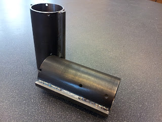
With a completed frame, it was time to push together the weapon. It was composed of four main parts: the drum, the motor can, the stator mount, and the outboard endcap. I had previously intended on having Whyachi machine my drum, but after telling me they couldn't make it or it would cost me $400, I decided to pursue alternate methods.

The drum design then simplified drastically. Instead of the unibody drum, the drum became an assembly of steel bars welded to a grooved tube. There were several competition teams and ME staff that could help me weld so I would save oodles. Plus, I could machine all the parts myself on the mill, lathe, and waterjet. Hardening could be achieved through begging to Braddock Metals in Atlanta, or utilizing a kiln we dug out of a dumpster by the physics building. It was a solid plan.

4130 was selected for the drum body, and 8630 (keyway stock) was selected for the teeth. Both are chromium-molybdenum steels that anneal, harden, and temper at the same temperatures (according to the ASM materials handbook). Plus they were cheap. About $20 for the drum so far.

Some hours of machining later, I had prepped the drums and teeth. Buying 1 ft of material from Online Metals was enough to two drums. No harm in spares right?


The drums were welded together by my friend Craig Wooden. Thanks Craig!

At this point I had put off drum construction that I needed to harden it immediately or run unhardened for the event. This meant I had to use the kiln. Some experimental jiggling of the analog temperature dials found a nice ~1650 deg F of oven temperature. I weaved some magnet wire in between the drum holes for handling since copper melts at higher temperatures than 1600. I placed the drum inside the oven and let it bake for ~2 hours. Then this:


Water bath instead of oil for safety reasons. I think I may have taken too long to transport the piece from the oven to the water. It had a nice oxidation layer that cracked off from expedited rusting.


However, we still observe evidence of hardening via auditory means. A smaller hammer tapped on the side of the hardened drum produced a higher pitch ring than the unhardened one. This is indicative of a tighter packed atomic structure, or a harder material in this case.

The other parts came together as easy as cake. I turned by best piece yet and was able to keep a 1 thou tolerance on all dimensions. The magnet can was simply pressed down inside the can. Lets hope I never need to remove that piece...


... but I did.


This point shows the robot completed and playing with some objects and Michael Jeffries' 30lber Nyx, but little did I know it was nearly a half pound overweight. I took it to the post office to weigh it the week before the event and yeah.

Massive disassembly time and uber machining mode. Each system and component was weighed to determine how much I would need to remove to make weight. Things like motors and electronics could not be changed and were simply held as a minimum weight sum. The drum weighed a whopping 26 oz with motor and all. Because steel was the densest material on the bot, it would receive the machining operation first.

The can was lightened as much as possible by turning away massive aluminum voids. The drum's teeth were castled down to the drum wall. There were some sections of the teeth that had me worried about the penetration of the welds, but this would not be the time to worry about them.

The wheels received a significant amount of attention as well. The wheels, belts, and pulleys weighed about 3.5 oz which is still a butt-ton for the beetleweights. Instead of using bronze sleeve bushings and aluminum hubs, I opted for a single piece Delrin hub. It was light, easily machined, and had semi-lubercative properties which meant I could save on bushing weight. The wheel rubber themselves were recut with some lightening holes along the radius.


Hey check it out! Tweels! I was skeptical about their impact resistance and damping effects on the robot's drive, but it worked well for the time being. Final weight for wheels, belts, and pulleys now sat at ~1.3 oz.

After replacing the metal top and bottom plates with 1/32" polycarb and garolite (so sad!) the robot tips the scale at 48.1 oz. Both mid-plate supports were removed to make weight.

The final shots.


Some nice vinyl logos and a Invention Studio temporary tattoo prepares the bot for screen time. Lets hope vinyl doesn't weigh much. I also prepared some plastic shims as anti-wedge devices. Instead of using the easily-damaged nylon, I opted for .022" thick UHMW. It seemed flexible, but hopefully not too deformable.

July 14th: Competition Day


Michael Jeffries of Near Chaos Robotics was nice enough to drive me up to North Carolina. Clash of the Bots was held at the Scheleiele Museum. A nice indoor, ventilated venue with plenty of space and power was provided. Team pit tables were predetermined and a specific table near the back door was dedicated towards charging lipoly batteries. It was very well organized. I was fortunate enough to be stationed near the arena.


As usual, I didn't take many pictures, but other people did.

Match 1: Ramvac

Without much driving practice going into this match, I was a bit nervous. I've seen this robot time and time before and Sam is without a doubt a good driver. Ramvac itself was a very sturdy wedge. It used 4 of the same modified drive motors I had so it was fast and powerful. It features a UHMW frame with hardened steel on the important parts. I knew I would not be able to go for the knockout, but I would have to use gyro dodges to my advantage to out drive him and score points.


I learned from this match that I should never never never get flipped over at all possible. The weight distribution of the robot made it very front heavy, and inverted driving was abysmal. I think I am fortunate Ramvac decided to revert my robot.

Match 2: Weta

Pete has been competing robots for quite awhile, so I expected a well polished machine. This particular robot is actually available as a kit from his website Kitbots. Conclusion: this must be a good machine. I'm not sure about the particulars on Weta anymore, since Pete mentions he was experimenting with new drive motors and a faster motor. I decide this would be an opportune time to test the max speed of my drum as well.


Let's not do that again. It appears his beater bar is in fact faster and caused me to get flipped. I spend over half the match on my head but am luckily reverted to make an astounding comback in the last 30 or so seconds. If Weta was using his old drive system, I might have been in trouble.


He dented my Ti armor :(

Inverted driving is a capital item to be addressed before Dragon Con! At least we see how effective the angled plating is in deflecting blows.

Intermission: Robot Panic

When I placed Dom into the box to face Shame Spiral, I noticed that only one drive side was responsive. The other ESC emitting the "no signal" or "out of center" error. I am forced to use my postponement to discover the error. All wires a nice and glued in (what a pain) with no connections lose. I decide to remove DDT's receiver and run the bot off two receivers, assuming the ch2 on my Spektrum Ultralite had failed. However, I eventually discovered my ch 2 on my repaired dx6i had died. Julie from Near Chaos Robotics lent me her tx for the remainder of the competition. Thanks Julie!

Match 3: Shame Spiral

A tough wedge of shock-mounted UHMW and hardened steel outer surfaces (actually harder than my expected drum hardness). I had fought Shame Spiral before at Dragon Con and was easily defeated by Thomas' driving skill and well designed deflective wedge. I hoped this time that my increased speed and anti-wedge devices would allow one good hit to invert him, where I would then leave him for the remainder of the match. I received none such luck.


Despite hits to his sides, none were able to grab and toss. As a result, I was never able to get him off the ground. Through all the abuse, my power plug (a deans micro) falls out and I tap.

Match 4: Ramvac

I was more confident this time, knowing that I had won a match against him before. However the Tx business set back the beetle brackets pretty far and I had minimal time to charge. I would have to take it easy this time and line up good shots on his sides or back.


Match 5: Grande Tambor

The expedited beetle bracket takes it toll. I had only 10 mins to charge this time, but I decided some match was better than none. This would be the ultimate test of my armor as Grande is a hard hitter and I expected a few outages during the match from undervoltage.


Every time Dom pauses is a drive esc reset. There wasn't really much I could do except wait to reconnect. I confess I believe it is a terrible way to be eliminated, but the angled armor held up well and given all issues are resolved Dom will be back for a rematch!

Well, after I fix this:


Post-competition analysis:

Clash of the Bots 3 was a tough competition with a lot of great robots. Dominant mode went 3-2, which is actually the worst record I have ever had for a new robot. No longer can I depend on the knockout win, I actually have to start buying spare batteries. I also need to investigate the control losses during the match. Its possible the battery is the issue, as in the current draw from my motors, but it could also be a need for more bus capacitance. I will have to revisit my electronics to determine the cause of these mysterious power outages.

Conclusion, Dominant Mode is a keeper! It would be nice if I could reallocate more weight to the rear of the robot such that inverted driving was more effective. I also need to make sure the pinions never disconnect from the KW motors. I will be contemplating fixes for the drum's bearing setup, but I think that hit from Grande was an exception, since I was not spinning. I will however be buying more batteries in reflection of the short charge times.

Thanks to Robert of Mad Overlord, we also have high-speed camera footage to download for a limited time only!

I also want to thanks Mike Gellatly of Busted Nuts Robotics for helping to machine some semi-complex aluminum angle blocks for Dom's side armor.

Soldering A123 Cells

Starting a new project, I would love to put some of the donor A123 cells to use. The studio's spot welder is nice, but we are currently too inexperienced to do a good job.


Unless you want crater packs.

Given the rather complex pack geometry, that leaves really only one option: soldering.

The anode and cathode of A123 cells are not made of the same materiel. The cathode appears to be made of nickel and the anode is made of aluminum. From experience you may know, one is easy to solder to and the other is not. 

If you dont have a huge iron, you'll have to resort to other creative methods. Charles Guan was visiting that weekend and devised a interestingly ballsy method of soldering to the aluminum end of the cell.

DOUBLE IRON METHOD

Materials Required
  • Two Soldering Stations. Chisel tips preferred (surface area)
  • Rosin Core Flux pen
  • Solder (of course)
  • Rough Sandpaper. 100-200 grit works fine
  • Helping Hands or some Cell Holder (advised but not required)
step 1: heat two soldering stations to very very very hot.

step 2: use the sandpaper to rough up the surface.

step 3: place one iron on the cell end and feed solder onto the surface until a reasonable glob forms. The glob should have the appearance of having adhered to the surface (whilst we know it isn't enough).


step 4: use the flux pen to paint the entire cell surface. be generous in covering the solder glob and adjacent areas.


step 5: take both irons and heat the solder glob at once. Wiggle (or jiggle f you feel) the double iron assembly about the surface of the cell. The solder should begin to melt instantly and flow across the surfaces where flux was applied. 


step 6: repeat for X number of cells.

Here is a video of the last step.


Enjoy!
Viewing all 48 articles
Browse latest View live